chadande
New member
- 163
- 1
- 0
- Location
- Eau Claire, WI
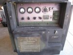
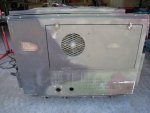
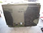
Well, I picked up my first surplus generator and luckily it appears I did OK.
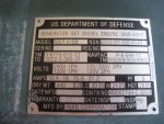
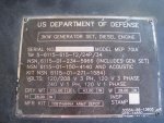
It is a 1988 MEP-016B that I assume had the ASK installed when new based on the “88” in the 701a serial number. It has a 2010 battery with a good charge and fresh clean oil in the crankcase. 591 hours on the meter.
I splashed some fresh diesel in the tank to get the float lifted and it fired right up. I ran a small load of 1000w for 15 minutes and saw no significant voltage or frequency variance. I was using both the gauges on the unit and my kill-a-watt meter. Everything appears OK with the exception of battery charging.
Yes, I have read many posts and gone over both of the downloadable TM’s. These two resources have answered the majority of my questions and I feel comfortable with basic operation and maintenance, but I still have a couple questions for those of you who know more about how these sets work:
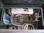
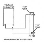
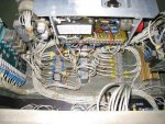
#1 Testing at the battery posts / slave receptacle shows 25.7v both running and not running which indicates the charging circuit is not working properly or at all. The TM shows to check voltage from the regulator at two test points on connector block A1-TB1 which is on the right side of the box (and has no #9), however the four wires from the regulator are connected to 3, 4, 5 & 9 on the block on the left side of the box. I see where the voltage regulator is, and where the wires go, but need help with which two to test.
#2 Inside the front panel only fuse F2 is connected to the convenience outlet, F1 appears to have never been soldered. Is that typical?
Thanks for any info in advance!

Attachments
-
63.6 KB Views: 53
-
57.1 KB Views: 53
-
44.8 KB Views: 53
-
67.4 KB Views: 56
-
85.2 KB Views: 66
-
85.8 KB Views: 53
-
12.7 KB Views: 50
Last edited:


