- 4,042
- 6,775
- 113
- Location
- MA
Looks like they must have run this unit to power a hair straightener only... gross.
Steel Soldiers now has a few new forums, read more about it at: New Munitions Forums!

Looks like they must have run this unit to power a hair straightener only... gross.
So, now that you pulled the head, does the crankshaft rotate?
Howdy,
Take a look through this thread Picked up 3 MEP-802A gensets and will be documenting making them all runners here
Peter went through the units and documented all the things he did. Very informative with the soaking, moving, soaking, timing etc.. to free them up.
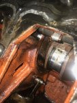
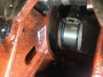
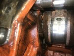
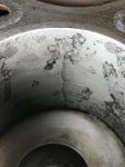
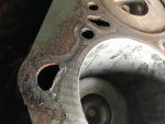
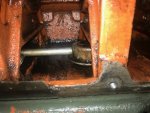 Digging in deeper-I poured evaporust on top of pistons this morning. #1 drained by the time I got home tonight. 2,3,4 are holding steady. Still no movement at all. Decided to pull the side cover and see what I could see. Lots of crud in the sump. Some rusting visible on the main bearing area. I am frustrated that I can't get any movement out of this thing. I don't know where else to try manually turning it besides what I am doing on the flywheel. I have sprayed and soaked the areas I can get to on the main bearings and also removed #2,3 bearing caps. Can not get to 1 and 4 due to the position they are in. This thing is really stuck and so am I!!!!
What about using a block of wood to "gently" tap the top of the pistons and see if it breaks the rust weld? By all things seen, the engine is going to have to be completely torn down, cleaned and parts replaced. Hopefully the cylinder walls are salvageable. Keep us updated. Good pics!!View attachment 718589View attachment 718590View attachment 718591View attachment 718592Digging in deeper-I poured evaporust on top of pistons this morning. #1 drained by the time I got home tonight. 2,3,4 are holding steady. Still no movement at all. Decided to pull the side cover and see what I could see. Lots of crud in the sump. Some rusting visible on the main bearing area. I am frustrated that I can't get any movement out of this thing. I don't know where else to try manually turning it besides what I am doing on the flywheel. I have sprayed and soaked the areas I can get to on the main bearings and also removed #2,3 bearing caps. Can not get to 1 and 4 due to the position they are in. This thing is really stuck and so am I!!!!
Since you could not find the procedure for main gen removal, here is a copy of the first page. Its page 185, (PDF reader) Its listed in the Index, under: ENGINE AND GENERATOR ASSEMBLY.
3-6 ENGINE AND GENERATOR ASSEMBLY.
3-6.1 Removal.
a. Shut down generator set.
b. Remove batteries, paragraph 2-12.2.
c. Remove screws (2, FIGURE 2-20), washers (3), and fan guards (4) from both sides of generator set.
NOTE
If removing the generator only, proceed to step f.
d. Drain engine oil into suitable container.
e.
f.
g.
h.
i.
j.
k.
l.
m.
n.
o.
If engine has been operating and coolant is hot, allow the engine to cool before
you slowly loosen radiator filler cap and relieve pressure from the cooling sys-
tem. Failure to observe this warning could result in severe personal injury.
Drain coolant into a suitable container.
Remove control box top panel, paragraph 2-16.1.
Remove top housing panel, paragraph 2-17.1.
Tag and disconnect wires at terminal board TB3 (16, FIGURE 4-11) leading from generator.
Remove nuts (1, FIGURE 2-26), Iockwashers (2), washers (3), and bolts (4) securing load output terminal
board assembly (13) to skid base.
Remove nut (5, FIGURE 2-9) and bolt (4) securing center door post (6) to skid base.
Remove bolts (7), nuts (, Iockwashers (9), and washers (10) securing lower door sill (11) to skid base.
NOTE
If removing the generator only, proceed to step n.
Remove bolts (18, FIGURE 2-, Iockwashers (19), washers (20), bolts (21), and nuts (22) securing air deflec-
tor panels (23), (24), and (25) to front housing (49).
NOTE
Fan shroud is in two pieces.
Remove bolts (13, FIGURE 2-20) and nuts (14) securing fan shroud (15).
Loosen two clamps (2, FIGURE 2-19) and remove hose (3) from air cleaner (7) and air intake manifold.
NOTE
If removing the generator only, proceed to step p.
Remove muffler, paragraph 2-65.1.

