• Steel Soldiers now has a few new forums, read more about it at: New Munitions Forums!

  • Microsoft MSN, Live, Hotmail, Outlook email users may not be receiving emails. We are working to resolve this issue. Please add support@steelsoldiers.com to your trusted contacts.


Need help identifying wire 5A to finalize 210 amp alternator conversion

Outfitters

New member
20
1
0
Location
Guntersville Alabama
My install is complete...but before I hook up the batteries and test the system I would like to get some confirmation from the experts.
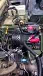
My wire 5A has no label...middle of the photo...above the large red boot...it has red heat shrink on it and it is attached to the IGN on the regulator and appears to be 8 gage. I am almost certain this wire is 5A....please verify.
This wire was the alternator out for the old 60 amp alternator... I have read that the 200 amp does not send power through the PCB (I have just installed a Nartron Smart Start System with yellow band GPC (and new glow plugs).
I am confused how this wire "changes function" when the alternator is upgraded to the 200 amp from the 60....(it was the alternator output and now is the IGN?)
Thank you in advance for your timely replies.
 

Attachments

Outfitters

New member
20
1
0
Location
Guntersville Alabama
well that unlabeled wire must be the 5A since everything is working perfectly now! It sure is nice to wrench and have the outcome work as planned... I am still confused how the output wire from the 60 amp alternator becomes the IGN wire when the 200 amp alternator conversion is done. I would really like to know if someone has a way of explaining it without requiring me looking at electrical schematics.
 

Action

Well-known member
3,581
1,552
113
Location
East Tennessee
Could it be that the wire only puts out power when the starter switch is in the RUN position? Or when the engine is running. It doesn't have to mean the wire goes TO the ignition.
 

desmodromic

Member
235
22
18
Location
New York, New York
well that unlabeled wire must be the 5A since everything is working perfectly now! It sure is nice to wrench and have the outcome work as planned... I am still confused how the output wire from the 60 amp alternator becomes the IGN wire when the 200 amp alternator conversion is done. I would really like to know if someone has a way of explaining it without requiring me looking at electrical schematics.
Any other theories in response to the above question?
 

cwc

Active member
Steel Soldiers Supporter
303
144
43
Location
Sweeden, KY
Wire 5A connects to wire 81A through the PCB/EESS box. Wire 81A is connected to the starter positive post, which is connected directly to the battery 24V+ post. When the logic is satisfied to make the relay in the control box close, then 5A is connected to the battery 24V+ post. So it can either provide a signal to the alternator (as in the case of the 200A Niehoff) or carry the charge for the batteries for the lower-amp alternators. Note that the wire size is at least 8 gage through the entire circuit from the battery to the alternator. The 8 gage wire is overkill when it is just providing a voltage signal.

Here is a section of the wiring diagram showing this connection (this is the "Kascar" diagram with 200A alternator):

Wire 5A on wiring diagram.jpg

In this context, the term "Ignition" or "IGN" should be understood from the perspective of the alternator, not the engine. The Ignition terminal gives the alternator a signal so that it can function and in a sense it "ignites' it.
 
Top
AdBlock Detected

We get it, advertisements are annoying!

Sure, ad-blocking software does a great job at blocking ads, but it also blocks useful features of our website like our supporting vendors. Their ads help keep Steel Soldiers going. Please consider disabling your ad blockers for the site. Thanks!

I've Disabled AdBlock
No Thanks