Before I installed the Fuse Mod
View attachment 822856
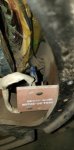
After the Fuse Mod. Also note the small blue varistor between terminals 7 and 8 on the voltage regulator. This is a separate but highly recommended mod that helps protect the VR from voltage spikes.
View attachment 822857
Personally I find the Military TM's are very thorough on diagnosing. (Looking through them myself it looks like you did the steps listed in the Operators Manual TM-9-6115-642-10)(TM-9-6115-642-24 is much more detailed for this kind of problem)
21. AC VOLTMETER (VOLTS AC) DOES NOT INDICATE VOLTAGE.
Step 1. Test defective AC Voltmeter (VOLTS AC), paragraph 2-46.2. a. If AC Voltmeter (VOLTS AC) is not defective, do Step 2. b. If defective, replace AC Voltmeter (VOLTS AC), paragraph 2-46.
Step 2. Test for defective AM-VM transfer switch, paragraph 2-52.2. a. If AM-VM transfer switch is not defective, do Step 3. b. If defective, replace AM-VM transfer switch, paragraph 2-52
Step 3. Test for defective VOLTAGE adjust potentiometer, paragraph 2-48.2. a. If VOLTAGE adjust potentiometer is not defective, do Step 4. b. If defective, replace VOLTAGE adjust potentiometer, paragraph 2-48.
Step 4. Test for defective AC voltage regulator, paragraph 2-27.2. a. If AC voltage regulator is not defective, do Step 5. b. If defective, replace AC voltage regulator, paragraph 2-27.
Step 5. Test for defective voltage reconnection switch (S
")
, paragraph 2-64.3. a. If voltage reconnection switch is not defective, do Step 6. b. If defective, replace voltage reconnection switch, paragraph 2-54.
Step 6. Check AC Voltmeter circuit for breaks or loose connections, refer to Wiring Diagram F&2. If breaks or loose connections are found, repair circuit.
This is from Page 65 in the -24 TM.
You've made a good start but it looks like you've only done Step 1 and Step 6 + some stuff on the DC side.
22. GENERATOR SET FAILS TO GENERATE POWER. Step 1. Test for defective ac circuit interrupter relay (K1), paragraph 2-61.3. a. If AC circuit interrupter is not defective, do Step 2. b. If defective, replace AC circuit interrupter, paragraph 2-61.
Step 2. Test for defective Field Flash relay (K15), paragraph 2-33.2. a. If defective, replace Field Flash relay. b. If Field flash relay is not defective and trouble persists, notify next higher level of maintenance.
I'd like to add step 2 on this one, but as I understand it the relays rarely go bad. Though if it is bad I can link you to an aftermarket one that works as a drop in replacement.
kloppk is the person WWRD99 mentioned earlier, he makes a remote start and monitoring kit, aftermarket (and improved) voltage regulator, and a replacement frequency trip switch (s14)


.jpg")