• Steel Soldiers now has a few new forums, read more about it at: New Munitions Forums!

  • Microsoft MSN, Live, Hotmail, Outlook email users may not be receiving emails. We are working to resolve this issue. Please add support@steelsoldiers.com to your trusted contacts.


New alternator but still problem.

Kenneth Cole

Active member
179
40
28
Location
Wapiti Wyoming
HI
Replaced the voltage regulator and brushes but still in the yellow. Measured voltage at the voltage regulator with her running and measured 24 volts.
Question? Am I reading just the battery voltage at this point? Is there a way I can measure just the alternator output?
Other ideas?

Ken
 

TOBASH

Father, Surgeon, Cantankerous Grouch
Steel Soldiers Supporter
3,258
2,989
113
Location
Brooklyn, NY
HI
Replaced the voltage regulator and brushes but still in the yellow. Measured voltage at the voltage regulator with her running and measured 24 volts.
Question? Am I reading just the battery voltage at this point? Is there a way I can measure just the alternator output?
Other ideas?

Ken
please remind us of what alternator and if appropriate did you adjust the screw?
 

Mogman

Moderator
Staff member
Moderator
Steel Soldiers Supporter
5,906
8,228
113
Location
Papalote, TX
Have you made sure you have the alternator excited? Wire 5A
If you have alternator output it will be higher at the output wire than 24v, mid 28s is what you are looking for.
Check and make sure you have 24V at 5A, basically that and a connection to the batteries on the large wire is all you need.
 

Mogman

Moderator
Staff member
Moderator
Steel Soldiers Supporter
5,906
8,228
113
Location
Papalote, TX
please remind us of what alternator and if appropriate did you adjust the screw?
If he has brushes it is a 60A, not sure you can turn down a working 60A to 24V, I would think 26 or so would be the lowest it would go.
 

Mogman

Moderator
Staff member
Moderator
Steel Soldiers Supporter
5,906
8,228
113
Location
Papalote, TX
HI
Replaced the voltage regulator and brushes but still in the yellow. Measured voltage at the voltage regulator with her running and measured 24 volts.
Question? Am I reading just the battery voltage at this point? Is there a way I can measure just the alternator output?
Other ideas?

Ken
Also what do you mean "measured at the voltage regulator" you should be measuring the voltage at the large terminal stud.
The system is very simple, alternator grounded (bolted to engine) exciter voltage on 5A and measuring the output at the large stud.
Check the voltage at the stud before starting but with the run switch on and you should see battery voltage (24V) at the large stud and 5A
If all that checks out and it still is not charging then the alternator/regulator is defective, there is an adjustment on the regulator but I do not think it has a very large swing one way or the other, I think counter clockwise is UP
 
Last edited:

Mogman

Moderator
Staff member
Moderator
Steel Soldiers Supporter
5,906
8,228
113
Location
Papalote, TX
Also make sure 5A and 2a are not swapped, 2A goes on the smallest stud, 5A should go to the stud marked sense
 

Kenneth Cole

Active member
179
40
28
Location
Wapiti Wyoming
Hi
Gentlemen, I made a mistake in the title. I replaced the voltage regulator not the alternator. I have a 60 amp unit. I will check out the 5a wire. Also I did not adjust the screw. Is this to adjust the voltage output?

Ken
 

Mogman

Moderator
Staff member
Moderator
Steel Soldiers Supporter
5,906
8,228
113
Location
Papalote, TX
Hi
Gentlemen, I made a mistake in the title. I replaced the voltage regulator not the alternator. I have a 60 amp unit. I will check out the 5a wire. Also I did not adjust the screw. Is this to adjust the voltage output?

Ken
Yes
 

Kenneth Cole

Active member
179
40
28
Location
Wapiti Wyoming
Hi
OK, I adjusted the screw on the voltage regulator and it made no difference in the voltage. I have 24 volts going to the regulator and I am reading 24 volts on the alternator. Could you tell me what the small ring terminal wire on the alternator is for and if it should have any voltage reading on it.
One thing I failed to mention is the reason I replaced the regulator in the first place was I was getting readings that would go from the yellow then into the green and stay there and then it would go back into the yellow. this was with no apparent pattern. So that is why I wonder if the alternator is really bad. Not that I know anything.
I plan on pulling the regulator off and make sure everything looks ok and that the new brushes look like their seated ok.
One more thing, the three push on connectors from the regulator to the alternator there is always the chance that I could have got them connected wrong. Is there some why to know where each wire goes.

Thanks
Ken
 

Mogman

Moderator
Staff member
Moderator
Steel Soldiers Supporter
5,906
8,228
113
Location
Papalote, TX
Sorry, I am ass backwards, standby, it has been a long time since I messed with a 60A. I THINK I am up to speed.
the 8GA wire 5A goes to the large stud, this is battery on the 60 but is sense on the 100/200A, 5A on the 60A like the sense wire, 568 is switched by the EESS and not hot all the time like one would find on a civy alternator.
2A is the small stud and that is AC tap, you should read AC on this terminal when charging, not a big factor at this time, will have nothing on it if the alternator is not working.
568 is THE sense or exciter wire on the 60A, that is the one with the pigtail and it should have 24V when running to excite the alternator.

I am VERY sorry for the confusion, I am surprised someone did not jump in here and correct me...

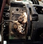
IMG_20220524_182618383.jpg
 
Last edited:

Mogman

Moderator
Staff member
Moderator
Steel Soldiers Supporter
5,906
8,228
113
Location
Papalote, TX
So to sum up, 24V on 5A, the large stud and 24V in the pigtail, 568 and no charging would mean a defective alt/reg.
 

Kenneth Cole

Active member
179
40
28
Location
Wapiti Wyoming
Hi
I pulled the voltage regulator off. There are 4 spade connectors on this regulator and just three wires from the alternator. I may have installed them to the wrong locations. Is there something showing where these should be connected? I may have to get another regulator. You think I would learn to mark the wires beforehand.

Ken
 

Mogman

Moderator
Staff member
Moderator
Steel Soldiers Supporter
5,906
8,228
113
Location
Papalote, TX
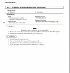
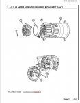
The TM shows 4 wires, there is no instructions on what wire goes where so I would assume they are marked.
There may be a more comprehensive TM....
60A.JPG
60A1.JPG
 

Mogman

Moderator
Staff member
Moderator
Steel Soldiers Supporter
5,906
8,228
113
Location
Papalote, TX
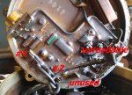
Well it is pretty straight forward, wire #1 on the first terminal, wire #2 on the second terminal and I can only assume wire #4 on the forth terminal but without some work it is unreadable.
IMG_20220525_132308057.jpg
YEP! it was time to change that 60A out for a 200A which is what I did, the 60A has been and will continue no doubt to be a troublesome device!
 

papakb

Well-known member
2,288
1,185
113
Location
San Jose, Ca
The older AMA 5102 alternator used a regulator with 4 pins while the current AMA 5104 uses 3 spade connections. Unfortunately they look pretty much the same. Did you install the right one?
 

Kenneth Cole

Active member
179
40
28
Location
Wapiti Wyoming
Hi everyone
I lucked out. I did have the wiring wrong from the regulator to the alternator. I corrected it and I am now running in the green.
I want to thank everyone for your help. If it wasn't for this forum I would be at a loss several times.

Thanks again
Ken
 

Mogman

Moderator
Staff member
Moderator
Steel Soldiers Supporter
5,906
8,228
113
Location
Papalote, TX
Hi everyone
I lucked out. I did have the wiring wrong from the regulator to the alternator. I corrected it and I am now running in the green.
I want to thank everyone for your help. If it wasn't for this forum I would be at a loss several times.

Thanks again
Ken
Glad you got it straight!, sorry again for the earlier misguidance.
The 100/200 use the 5A wire to excite the alternator and sense wire, the 568 wire cannot supply enough current to excite the 100/200A alternators and is capped off with a blind plug and tied back to the harness.
 
Top
AdBlock Detected

We get it, advertisements are annoying!

Sure, ad-blocking software does a great job at blocking ads, but it also blocks useful features of our website like our supporting vendors. Their ads help keep Steel Soldiers going. Please consider disabling your ad blockers for the site. Thanks!

I've Disabled AdBlock
No Thanks