• Steel Soldiers now has a few new forums, read more about it at: New Munitions Forums!

  • Microsoft MSN, Live, Hotmail, Outlook email users may not be receiving emails. We are working to resolve this issue. Please add support@steelsoldiers.com to your trusted contacts.


New dash GEN1 GEN2 workaround ideas.

FridgeBrilliance

New member
69
0
0
Location
Tacoma, Washington
Ok, so things have gotten to the point with the new sheet metal dash where all I have to do is figure out what to do with the gen lights. I almost screwed the pooch and committed to converting to 12V just because of this, then the poltergeist that is doghead invaded my dreams and admonished me and mandated that I find a better solution.

So, what I would like to do, since they have to remain indandescent (everything else will go to LED if that is possible, IIRC only the gen 1 and gen 2 light must be) is use something like this:

2905

Problem is, I have no idea what to search for, or if there is even anything like this that will hold the correct bulb. Any ideas?
 

cliffyp

Member
328
3
18
Location
Brownsville, Texas
I have no idea if I'm right but it would seem like you could snip the wires for the gen lights before they get to the instrument cluster and reroute them to another location for a light instead of them flowing into the board behind the cluster. I guess you would still need to use a bulb that offered the correct resistance but it doesn't seem like there's any other reason the flow would have to go into the board on the back of the instrument cluster. Warthog, I'm I right on this or way off?
 

FridgeBrilliance

New member
69
0
0
Location
Tacoma, Washington
The board is getting completely eliminated. My main concern is maintaining that resistance so that the 24v circuit works as intended, and I have some sort of mounting solution that will work for those lights while maintaining an overall military issue appearance.

The whole dash is a sheet of aluminum, with all VDO gauges that will use new sending units, all other lights like the turn signals will go to LED. The shop that is doing the actual wiring and sender work assures me that the whole PCB can be eliminated.

What I do not know how/what to look for is appropriate sockets/housings for the bulbs.
 
Last edited:

MarcusOReallyus

Well-known member
4,524
811
113
Location
Virginia
  1. Measure the resistance of the stock bulb.
  2. Go to Radio Trash and buy two resistors of the same value as the stock bulb.
  3. Install the resistors somewhere behind the dash where you can service them if needed. (HIGHLY unlikely!)
  4. Use an LED to indicate correct function of the alternators.
Now you have resistors to keep your alternators happy, and your dash is all nice pretty LEDs.


BONUS: Resistors are going to be FAR more reliable than bulbs.


Done.
 

Skinny

Well-known member
2,130
486
83
Location
Portsmouth, NH
I dig this idea but you can't use a bulbs resistance value because it drastically changes when you light it up. Measure amperage through the gen light instead. Then take the voltage and divide it by the amperage. This will give you the correct resistance value you need.

I'm sure if you googled it, I imagine someone has a writeup on Pirate or some hot rod forum. Wait...hot rod builders can't do wiring so they install a one wire alternator :)
 

Skinny

Well-known member
2,130
486
83
Location
Portsmouth, NH
Replacing vehicle alternator warning lamp with LED

Very good reading for something you are looking to do. I am very good with automotive electronics but am by no means an electrical engineer. Looks like these guys have discussed replacing the charge lamp with an LED and using the correct resistor as well.

I am really happy that Al Gore invented the internet. This was the first hit on a google search:idea: (can we get an LED emoticon?)
 

MarcusOReallyus

Well-known member
4,524
811
113
Location
Virginia
I dig this idea but you can't use a bulbs resistance value because it drastically changes when you light it up. Measure amperage through the gen light instead. Then take the voltage and divide it by the amperage. This will give you the correct resistance value you need.

You are right!


Tanks for the correction. :beer:
 

Skinny

Well-known member
2,130
486
83
Location
Portsmouth, NH
No problem!

As soon as I read that, I immediately could here my high school shop teacher yelling in my ear..."YOU CANT MEASURE BULB RESISTANCE TO CALCULATE AMPERAGE!!!!!!"

He was good at his job, I could only hope that I verbally assault my students enough for that to happen.
 
Now thats a thought.

Why deal with a bulb or LED at all? How about a volt meter or ammeter for each alt? Just a thought

Now a digital meter for each alt is that sounds awesome. VDO offers those i would think you could adapt one for that purpose.They offer the whole cluster with bezel for the 81-87 chevys.Expensive though.But the digital gauges one for each alternator would be a great addition.Though cant wait to see pics no matter what ya do.:]
 

FridgeBrilliance

New member
69
0
0
Location
Tacoma, Washington
2 Voltmeters would substitute the lights and the circuit would still work as intended? If so I would much rather go this route, though not with digital.

Thanks for the help and search-fu assistance guys. I really need to do some reading up when it comes to electrical systems, I am completely ignorant of how this stuff works.
 

MarcusOReallyus

Well-known member
4,524
811
113
Location
Virginia
You'd still need the resistor for functionality, but that's easy to do. They can be behind the dash, out of sight. Use the meters for telling you what's happening.

I will probably go this route myself. Using a bulb for resistance isn't the best design I've ever heard of.
 

FridgeBrilliance

New member
69
0
0
Location
Tacoma, Washington
Ok well when I think about "resistor", all I can envision is one of the little dinky bits I have to solder on, like you would see on a PCB, are we talking about the same thing? Or something substantial I can actually wire in?
 

MarcusOReallyus

Well-known member
4,524
811
113
Location
Virginia
You can crimp one it, or solder it. Depends on the size you need. You do need to get them big enough to handle the current. When you've measured the current the bulb takes, multiply that by the voltage, and you'll have the watts that the resistor will need to handle. Radio Trash should have an assortment.

Here's an idea of what's available:

High Power Resistors,Manufacturer of Power Resistors,High Power Resistors Supplier,Power Resistors Manufacturers,India


Here's more info on the concepts:

Resistor Power Rating - Resistor Wattage Rating

Tell ya what: you measure the current those bulbs are drawing and post it here, and one of us will figure out what you need and reply back. I know there are a few, and probably quite a few, of us who are familiar with this stuff and can help you out.

Deal? :beer:
 

Warthog

Moderator
Super Moderator
Steel Soldiers Supporter
13,775
227
63
Location
OKC, OK
Why not use GM's repair guide to find the answer?

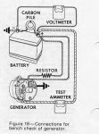
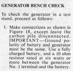
What the shops use to check the units is a 10 ohm resistor rated at 6 watts.

Read page 8 and look at the diagram.

It would be nice to have an indicator light.

As usual YMMV.


Bench Check.JPGResistor.JPGView attachment Alternator 27SI.pdf
 
Last edited:
Top
AdBlock Detected

We get it, advertisements are annoying!

Sure, ad-blocking software does a great job at blocking ads, but it also blocks useful features of our website like our supporting vendors. Their ads help keep Steel Soldiers going. Please consider disabling your ad blockers for the site. Thanks!

I've Disabled AdBlock
No Thanks