Site was a bit slow, sorry for the late reply...
Okay yeah we've definitely got a few plugs that aren't working because the manual glow plug circuit was not blowing a 40A fuse. Probably an answer to why she struggled to start in the cold sometimes.
I would say most assuredly,
YES.
Comments in-line in
Yellow:
So if I was to do as you suggested tim/antennaclimber, I would:
1) Connect a large gage wire (0 or 2?) to the battery directly <-- 2 gauge should be fine, it can carry up to 200Amps
2) Fuse it with a 100-120A fuse (assuming I am using 8 new AC60G's) <-- 150Amp fuse here, you want the expected max plus 25% to prevent "nuisance blows" (120Amps x 1.25 = 150Amps) This also helps if you change plugs later with different specs/current-draw.
3) Connect the fused hot to the relay on #30 prong
4) Connect outgoing large gage wire coming from relay #87 prong to orange leads to glow plugs
5) Connect ground #85 prong through momentary switch
6) Connect ignition supply to #86 prong on relay
Keeping the 100-120A current on this circuit in mind, will the OEM relay do the job? It's one of those NAPA big ones like for the DH starter mod...
There are many threads on the correct part number relay to use for the GP relay underhood (GPR109 or ST85 rings a bell) - as you can see 100Amps may be fine, but I really prefer a 200Amp rated, silver plated contact relay. Most of the 100Amp relays are copper alloy only, and with the assured high current at make/break, these contacts will wear out faster than I personally like. YMMV, others have had great success with the 100Amp relays, I like the extra design margin - thinking of it this way: "...If the GP circuit fuse is rated at 150Amps, and the relay contacts are rated at 200Amps, the fuse is still the only weak point in the circuit..." Again, YMMV...
The positive power should be from the ignition circuit (pink or pink/black-stripe - don't recall off the top of my head). There should be a wire under the hood somewhere near the brake booster where the GP relay is supposed to go - if it got cut off, you will have to go harness spelunking.

The light blue wire in the same general area should go back to your GP card, this is the wire that when the GP card grounds it, will complete the circuit through your GP relay.
If you're asking about terminal numbers, that tells me you're thinking about using a small Bosch cube-type relay - I've never seen one of these rated for over 50Amps, so that's a no go. A true high current relay like a GPR109 will have two very thick posts for the switched load, and two very small posts for the control coil.
IMHO it will be obvious which circuits go where.
![[thumbzup]](https://www.steelsoldiers.com/images/smilies/icon_smile_thumzup.gif "Thumbs Up [thumbzup]")
From my further reading on this subject in the last few weeks, I can surmise that one of the greatest killers of GP cards, is not removing both battery ground terminals when disconnecting the battery for servicing the vehicle. This will cause back feed through the transistor that controls the GP relay - which energizes the relay using the upper 12V battery that is still connected, burning out plugs by running them until the reverse current eventually burns out the transistor (killing the card). This makes it difficult to trouble shoot as many failures can happen at once due to inexperienced mechanics.
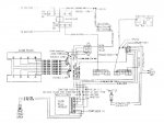
http://ww2.justanswer.com/uploads/Micharoe/2009-12-29_200141_86_diesel.gif
You might consider a controller retrofit if your stock glow control system is a total loss. I have no idea how easily it could be retrofitted to a CUCV, but it may be worth looking at. The system is simple and works well.
The relay/controller is a AIRTEX / WELLS 1R1332
This was the stock system on the civilian 6.2's. Personally I have a 1982 GMC that had a horrible glow control system that used a controller that threaded into the driver's side head and controlled a solenoid mounted on the fender well. I went to the newer system and have not had a single problem.
Before we get into that, let's take a better look at the OP's factory GP system - if we go down the modification path, we here on the site will be less easily able to help troubleshoot in the future, since it will not be a stock CUCV system. I think you can buy a GP card from AntennaClimber for less than what you can buy one of the newer controllers for - so if the card holder under the dash is still there, and at least 2" of wire coming out of the card holder is there - we can probably walk through repairing whatever was done to the truck.
A lot of times these trucks get modified because the previous owner didn't have the time or patience to figure out what was wrong with the stock system - it looks more complicated than it is I swear!!!