Unable to find an electrical diagram. To my understanding M916A3 has dual voltage alternator with main output as 12v and secondary low amp 24v to charge the batteries. Is the only 24v to the starter and mil spec trailer lighting connection with everything else 12V?
The -10 TM says this about the electrical system -
TM 9-2320-302-10 said:
ELECTRICAL SYSTEM
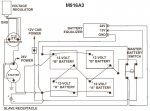
Four 12-volt batteries connected in series-parallel supply the 12-volt electrical system (Figure 5) and provide 24 volts for the starter motor, blackout lights, accessories, and trailer connectors. The system is charged by a 140- or 200-amp alternator. A voltage regulator, mounted on the firewall (M915A3 SN J21548 and below) or on the alternator (M915A3 SN J21548 and above, M916A3, M917A2), regulates the system voltage.
The M916A3 uses a pad mount 24v 140 or 200 amp alternator. The starter is 24v.
24v 140 Amp - Leece Neville BLP3312
24v 200 Amp - Leece Neville A0014964PA
The -20 TM that (probably) explains the particulars of the electrical system as far as what items use what voltage power is still not for public distribution. (You can own the truck, but can't know how to work on it

) I strongly suspect that the M916A3 is set up similar to other similar trucks - The starter, alternator, and military trailer lighting are 24v, with everything else being 12v. There might be some weird stuff in there like the CTIS or winch is 24v, I can't say for sure.
The 12v for the truck is provided through an Eaton/Cooper/Surepower 52210RB 100 amp 24/12v battery equalizer. This unit has been recalled and replaced with P/N 21100E00 due to fire issues.
Basic electrical Diagram below -

I have altered my M916 charging/electrical system to largely mimic the M916A3 setup, and it can be viewed here -
http://www.steelsoldiers.com/showthread.php?81412-Photos-of-My-M916&p=1800132&viewfull=1#post1800132


