• Steel Soldiers now has a few new forums, read more about it at: New Munitions Forums!

  • Microsoft MSN, Live, Hotmail, Outlook email users may not be receiving emails. We are working to resolve this issue. Please add support@steelsoldiers.com to your trusted contacts.

New member - I'm in it for the long haul - My BAe 2009 - M1093A1

coachgeo

Well-known member
5,143
3,461
113
Location
North of Cincy OH
I think I would rather have the drawbridge. Unless there is some lift mechanism we cant see this looks like it will take at least 2 people to raise and lower…
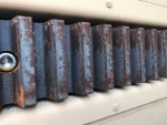
maybe it is lift and draw bridge? as in overhead winch lifts it to clear any deck upper pins from the track...Put a piece of ?? to push top of deck away slightly from track to keep top pins on each side from going back into track while lowering (tilts it outward at top a bit) .... then begin lowering via above winch causing bottom of deck's pins to re-seat home into a pivot point in both tracks. This would be followed by top of deck starting to swing/lower down to flat deck.

now if that is not how it works.... sounds like a clever way to build one though lol
 

StratoCrewzr

Member
44
88
16
Location
Arizona
I had a bunch of ideas on how things worked and quickly discovered things were even more genius when I was actually able to see it in person. You guys are very close to understanding how the back platform stows and deploys. Photos can't do it justice. I'll make a video of it one day.


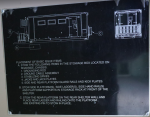
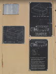
STOWAGE INSTRUCTIONS.png
(STOWAGE INSTRUCTIONS located on interior wall)


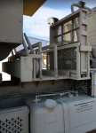
Railing and ladder storage.png
The STAIRS, RAILING, and SIDE PLATFORM are stored ahead of the Shelter and aft of the Cab. I wondered how the square platform could be held in place at either of the side shelter doors with stairs alone. Well it turns out, it can't. That is where the hanging rods come into play. Look aft of the railing in the pic above, and note the rectangular pinned door on the long enclosure.


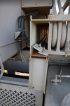
SUPPORT RODS.png
These RODS support the side door's platform (square stored platform in storage in pic above, between shelter and cab) by attaching to the platform and then attaching to the recessed hanging points located just left and right of upper side doors.


SUPPORTS SLIDEOUT.png

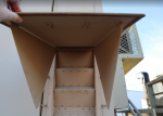
Now to address the AFT PLATFORM and how it deploys. Someone above, correctly stated that it has connection points that slide within the vertical rails to the left and right of the dual doors. There are a couple pins that lock the stowed floor in place as you see it above here. All these ladders and porches are light aluminum. No steel. So they are amazingly light, but sturdy. Its easy for anyone to carry any single stairs or platform by themselves.

The way this large platform/porch deploys downward is by first unpinning it, pulling out the center I-BEAM support (with the black star on it) as this is the piece that holds the two side supports in a locked position towards the truck. Then deploy the left and right support arms. These all provide the physical support for the porch in it's deployed position. Below is a photo showing the armored version of this truck and the square porch is actually being used as landing at the bottom of the stairs to likely support the stairs in the soft sand (preventing damage to shelter attachments) and to double as a shoe debris remover.

Now one or two people simply grab the bottom edge of the stowed platform and pull out and towards you. The top two sliders attached to the porch in inlayed into the vertical track will gently slide down and the entire porch is in place. Now you simply add the stairs to the porch and attach the railing. There is steel cabled flexible railing to attach to the porch to protect anyone from falling off the porch. There are attachment points to further attach the larger set of stairs and a handrail.

Inside the side stowage boxes, in addition to this flexible railing, are ground support stands that go into position not beneath the slide-outs, but the sides of the truck frame. They ONLY provide support to preventing the lateral rolling that would occur if multiple people were inside working and walking back and forth...because that is what it was designed to do.

TRUCK LATERAL SUPPORTS.png

original (5).jpg
Showing the flexible railing on platform/porch.

original.jpg
Showing square platform/porch as landing pad for starboard stairs. Also can see one of the vertical supports which keeps the truck from rocking.


Screenshot 2021-12-03 200317.png

SIDE ENTRANCE.png
Slide out can be cranked out/extended or retracted back in with the hand crank you see sticking out just below bottom left of porch. The I-Beam it penetrates allows for the handle to crank them out/in while stowed. Zach with "Bantha" uses a power drill to do this labor. The military used 19 year old privates. Very simple and robust mechanism.
 
Last edited:

StratoCrewzr

Member
44
88
16
Location
Arizona
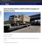
Found the article.

M1087 vs bridge article.png


Terribly sad. Only (3) Three M1087A1's with C7 etc in Civilian hands now....4 if you include this totaled one. I'd suspect impossible to reconstruct. Likely a decent parts donor.


😥
 

ramdough

Well-known member
1,554
1,729
113
Location
Austin, Texas

coachgeo

Well-known member
5,143
3,461
113
Location
North of Cincy OH
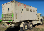
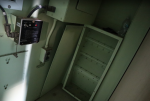
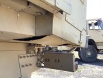
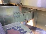
wonder if these are captured spring in the rear and fixed in front. Here is picture of rear mount from Gov. planet of the one that got scrunched via bridge and....... maybe the spring is housed in a tube?
 

Attachments

Ronmar

Well-known member
3,829
7,439
113
Location
Port angeles wa
wonder if these are captured spring in the rear and fixed in front. Here is picture of rear mount from Gov. planet of the one that got scrunched via bridge and....... maybe the spring is housed in a tube?
Springs or perhaps rubber compressible bushings…
 

StratoCrewzr

Member
44
88
16
Location
Arizona
That front mount picture is super useful!

Do you have any pictures of the rear mount? I really need to see that one.

Is the box resting on the truck frame? Or wood strip? Or rubber? Or air gapped?

Thanks!!!!!!!


Sent from my iPhone using Tapatalk
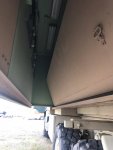
Glad it helped. I had to leave the truck with seller and won't be back to see it until early next year. According to the photo of the damaged rig (above) and from my memory of crawling around it, it's the same. I can't tell you if it's sitting directly on the frame or not but it does appear that there is either a soft rubber pad or aluminum sheet.

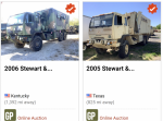
I should come clean here as well on the green camo 2006 M1087A1 in the Iron Planet link above. I'm the winner of that auction and will be shipping it down to where my Tan M1087A1 is. I know, it should be a sin to have two of these. Wasn't my intention. Bought the green camo one before I was aware the tan one was available. It's unlikely I'll be able to keep both in the long run, as much as I'd like to. It also turns out they'll both be in the best care imaginable for these next couple months. Turns out that the gentleman who sold me the Tan one is great friends with one of the top Stewart & Stevenson Design Engineers. This friend literally is the go to guy on why and how on almost every part and piece of the LMTV line. I plan to pick his brain when I meet him for dinner next month. I'll add this to my many questions.

I'll be flushing all fluids and changing most rubber hose lines on both trucks. Then either ship or drive them home to AZ. I plan to have one of the two M1087A1's at the 2022 Overland Expo in Flagstaff and Denver this coming year if anyone wants to see them in person.

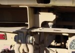
Here is the best I can do at this time for connection points.


Aft Connection.JPG


Aft Connection 2.JPG


Front Connection.jpg
 
Top