• Steel Soldiers now has a few new forums, read more about it at: New Munitions Forums!

  • Microsoft MSN, Live, Hotmail, Outlook email users may not be receiving emails. We are working to resolve this issue. Please add support@steelsoldiers.com to your trusted contacts.

New to me MEP-803A with a charred ground

2Pbfeet

Well-known member
433
772
93
Location
Mt. Hamilton, CA
Upfront, I just want to say how invaluable this forum is. I have been reading for a few years, and it gave me the confidence that I might be able to get an MEP-803A up and running.

Not there yet. But I bought one.

Backstory: I just picked up an '06 MEP-803A, with 22 hours on it. Given the age, and the low hours, I figure that something happened early in its life, and folks didn't have time to trouble shoot it, and it got parked out back.

Apparently it was originally a genset on a M151A2 for the 127th. At some point it parted company with the trailer.

I'm working my way through cleaning it up ( mouse nests, wasp nests), swapping in the well nut tank fix (it leaks diesel), changing all the fluids plus filters, and putting in @kloppk's upgraded voltage regulator.

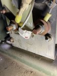
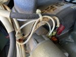
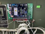
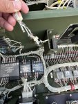
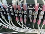
I noticed that the wire between the ground lug on the power panel and the engine frame is charred, (100E?). As in down to bare wire in some places, insulation missing in a number of places, and black and toasted along its length.

Where do I find what the correct wire gauge for 100E is? Any tips on sources? I'm sure it is obvious, somewhere, but I am still learning how the TMs function, and I can't seem to match that wire to a gauge or part number. I'm assuming that they are all made up from stock as needed. Needless to say, I can't read the markings on the actual wire.

Any thoughts on how someone might have toasted the ground wire from the engine frame to ground lug, and what else might be a casualty, or at least worth looking at?

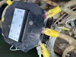
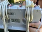
Some rodent also had fun chewing on what I think is the EMI shields between the power lugs. Is there a source for them, or a circuit? I think that it is the AFCON 88-20527, for the ground to neutral connection. (I believe it is a 0.5W 1Mohm resistor and a .1uF, plus a 1.0F capacitor.)

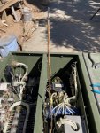
Finally, there is the remains of a nest behind the cube (S8). What is the best way into get there? Top and upper side panels off?

Thanks!

All the best,

2Pbfeet
 

kloppk

Well-known member
Steel Soldiers Supporter
2,148
3,527
113
Location
Pepperell, Massachusetts
Some rodent also had fun chewing on what I think is the EMI shields between the power lugs. Is there a source for them, or a circuit? I think that it is the AFCON 88-20527, for the ground to neutral connection. (I believe it is a 0.5W 1Mohm resistor and a .1uF, plus a 1.0F capacitor.)
Looking at the picture you sent me I believe it's the other filter F/N 33 which is PN 88-20530
 

Guyfang

Moderator
Staff member
Moderator
16,784
24,127
113
Location
Burgkunstadt, Germany
Take the top off. Then you will see into the space behind the control panel.
Take some pictures. In the other thread, (and you are not suposed to post more then one thread talking about the same problem) you said the wire "runs from the ground lug on the power panel and the engine frame". The 100E runs from the B1+, (starter) to the TB1, (Out Put Terminal Board) ground. Not the same. Even if you can not read the wire numbers, you can trace it from point to point.
 

2Pbfeet

Well-known member
433
772
93
Location
Mt. Hamilton, CA
My apologies for posting incorrectly, and for not describing the location accurately. The wire that I meant does run from the starter to TB1.
You can see the bare wire on the attachment side, as well as the chewed on filter(?).

Thanks again.

All the best,

2PbIMG_5205.jpeg
IMG_5207.jpeg
 
Last edited:

2Pbfeet

Well-known member
433
772
93
Location
Mt. Hamilton, CA
Stop!

On the burnt wire in the second picture, the wire number is 100E10. That means its a 10 Gage wire. My mistake. The wire size is always written at the end of the wire number.
Thank you eagle eye!

That is good news as it seems 10ga wire seems to be much easier to find. I'm still a little curious as to how someone put enough amps into that wire to char it.

I was looking at the first photo again, and I think that there is a terminal ring there on the neutral lug that doesn't appear to attached to anything. Time to pop that off and have a look with the schematic and see what else ought to be there.

Chipping away. I really appreciate the knowledge here. There is nothing like experts who have been there done that with thousands of units. Thanks.

All the best,

2Pb
 

Guyfang

Moderator
Staff member
Moderator
16,784
24,127
113
Location
Burgkunstadt, Germany
I have seen this failure before. Twice. Don't know what caused it, but first saw it in 2005(?) and at the time, no one could find wire #100E10 on the schematics, because it wasn't there! Then in 2007(?) I found a gen set at Reset, that had been taken apart, and put back together by different people. When they were done, they were standing there with wire #100E10 in the hand, and could not find out where it went. Again, because the schematics were wrong. At some point in time, the changes were made. But lots of the metal schematics riveted on the sets, are old, and still do not show the wire on it.
 

2Pbfeet

Well-known member
433
772
93
Location
Mt. Hamilton, CA
I have seen this failure before. Twice. Don't know what caused it, but first saw it in 2005(?) and at the time, no one could find wire #100E10 on the schematics, because it wasn't there! Then in 2007(?) I found a gen set at Reset, that had been taken apart, and put back together by different people. When they were done, they were standing there with wire #100E10 in the hand, and could not find out where it went. Again, because the schematics were wrong. At some point in time, the changes were made. But lots of the metal schematics riveted on the sets, are old, and still do not show the wire on it.
Ok. I find that is helpful. I can live with random stuff happens.

It did take me awhile on the schematics to realize that the wire was probaly E100. I wonder if part of the issue was that the wire is part of both the DC and the AC (ground) circuits, so neither fish nor fowl.

All the best,

2Pb
 

jamawieb

Well-known member
1,437
556
113
Location
Ripley/TN
Ive seen this on 2 sets before. It usually only affects that wire coming from the ground lug. on thing I can think of is someone hooking a hot wire to ground to cause a short. Noth cases I just ran a new wire from the ground lug to the ground at the starter.
 

2Pbfeet

Well-known member
433
772
93
Location
Mt. Hamilton, CA
So, I stripped the old 100E10 wire out, and replaced it. Pretty straight forward. I did notice that the ground terminal on the panel board is bolted through a 1/8"aluminum support to the frame, the same one that the ground to neutral bar bolts to. So, that would mean any AC miswiring would short to the frame via the plate. This leads me to I think that this charred wire might come from disconnecting the positive battery cable at the starter, and allowing that to short to the engine, leaving the only path to ground via 100E10. I guess a solenoid failure at the starter shorting to the engine frame would also do it. Regardless, I think it was a DC fault, and yes, improbable.

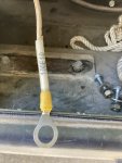
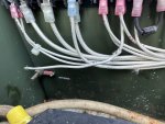
I clipped the 100E10 wire at the ground post to make it easier to remove. I wanted to check all of the adjacent wires in the cable bundles for damage, as I removed it. I did not see anything beyond some discoloration on adjacent wires which could have been from the 100E10 insulation toasting.
IMG_5250.jpeg
100E10 was intact, and the copper strands undamaged for the full length.
Lacking the military's snazzy wire labeler, I made do.
IMG_5251.jpeg
Finally, I finished up with replacing the original voltage regulator (it had not had the fuse modification) with @kloppk's modern regulator version, which was super easy thanks to great wire labels and instructions.
IMG_5253.jpeg Thanks @kloppk!

What should the top of the cube look like for sealing? The TM references sealant, and this unit had two short strips of the silicone weather stripping across the top of inner transverse walls, isolating the HV section.

The Optima redtops that came with it were dead, but some judicious charging and desulfation routine, brought them both back up to full charge. I have two pretty modern chargers, and neither one seems to be able to modulate the charging appropriately. (Schneider, and Black & Decker) I am going to watch them for a few days to see what the self discharge looks like before trying to use them.

I changed the oil as well, not knowing if it was break-in oil, or not, since the filter had been changed at 21 hours. On draining it looked greenish, but surprisingly black. I put the John Deere 30W break-in oil back in, with a new filter. On to coolant...

Thanks again everyone!

All the best,

2Pb
 
Last edited:

Guyfang

Moderator
Staff member
Moderator
16,784
24,127
113
Location
Burgkunstadt, Germany
What should the top of the cube look like for sealing? The TM references sealant, and this unit had two short strips of the silicone weather stripping across the top of inner transverse walls, isolating the HV section.

I never used sealer here. I had to take many tops off, and every one that someone used RTV, or anything like it, was a huge PITA getting the top off. AND, often bent the top when someone got frustrated. I never saw any reason for the weather stripping or sealer.
 

2Pbfeet

Well-known member
433
772
93
Location
Mt. Hamilton, CA
What should the top of the cube look like for sealing? The TM references sealant, and this unit had two short strips of the silicone weather stripping across the top of inner transverse walls, isolating the HV section.

I never used sealer here. I had to take many tops off, and every one that someone used RTV, or anything like it, was a huge PITA getting the top off. AND, often bent the top when someone got frustrated. I never saw any reason for the weather stripping or sealer.
Thanks! There is nothing like the voice of (extensive) experience.

All the best,

2Pb
 

odge

New member
17
11
3
Location
Prescott, AZ
Hello everyone, At the first of this thread 2Pbfeet said he was looking for some wiring. I to am looking for wiring but have not been able to find the 10ga or 20 ga wire needed to replace what's left of mine (rodent problem). Can anyone point me in the right direction?
 

2Pbfeet

Well-known member
433
772
93
Location
Mt. Hamilton, CA
Hello everyone, At the first of this thread 2Pbfeet said he was looking for some wiring. I to am looking for wiring but have not been able to find the 10ga or 20 ga wire needed to replace what's left of mine (rodent problem). Can anyone point me in the right direction?
Sorry about the rodent problems. Mine had a couple of nests in it when I got mine.

Try searching with your favorite search engine for "TGGT wire". Available from a number of vendors, plus the big auction site and on the jungle one. (TGGT is "PTFE Tape/Fiberglass Serving/Fiberglass Braid treated with High-Temp Saturant", aka Tape, Glass, Glass, Tape). It is rated for 250C/480F, which means that it has very different (higher) ampacity ratings compared to other wire insulations, if the connectors are also 250C rated.

Good luck! FWIW, I used adhesive heatshrink over labels to label the wire. Not as good as the military labeling system, I suspect, but better than nothing.

All the best,

2Pbfeet
 
Last edited:

odge

New member
17
11
3
Location
Prescott, AZ
I have some many pictures I could build a photo album. lol Will include some shortly i.e. when I figure out how to get them from my phone to my work computer and on here. Will also include some of wires that I have no idea where they go (completely chewed in down to the terminal end.
 
Top
AdBlock Detected

We get it, advertisements are annoying!

Sure, ad-blocking software does a great job at blocking ads, but it also blocks useful features of our website like our supporting vendors. Their ads help keep Steel Soldiers going. Please consider disabling your ad blockers for the site. Thanks!

I've Disabled AdBlock
No Thanks