- 1,046
- 45
- 48
- Location
- Syracuse, New York
I'm confused about the TM's instruction for crosshead adjustment. The first and second proceedure (example 3-16 and 3-63 below) both match and call for a dial indicator and setting of .025-.040. The third example, durning valve adj (3-83), is similar but lacks the dial indcator and preload of .025-.040. It says just turn the adj. screw until it hits the stem and then tighten the locknut.
This seems to be a conflict. Wouldn't the 3-83 adj just undo the preload added during 3-16 or 3-63 (with the dial indicator/.025-.040)?
(All three examples here are from the same section of the same TM)
-----------------------------
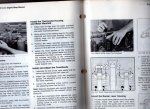
3-16. VALVE CROSSHEAD MAINTENANCE-
(TM 9-2320-260-34-1, page 3-47)
1. Coat crosshead (1) and cylinder head guide (5) with light film of lubricating oil.
2. Install crosshead (1) on cylinder head guide (5) with adjusting screw (2) pointing toward exhaust
manifold side of engine.
3. Hold crosshead (1) down so it contacts valve stem (6) on side opposite adjusting screw (2).
4. Turn adjusting screw (2) until it contacts valve stem (4).
NOTE
Ensure adjusting screw is just lightly seated.
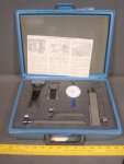
5. Place dial indicator over center of crosshead (1).
6. Press down on crosshead (1) and zero dial indicator.
7. Holding crosshead (1) down, turn adjusting screw (2) until dial indicator reads 0.025-0.040 in.
(0.635-1.016 mm).
8. Tighten adjusting nut (3) 22-26 lb-ft (30-35 N•m).
NOTE
If minimum clearance is not 0.025 in. (0.635 mm), turn adjusting
screw one-third the distance of one hex on replacement crosshead
and cylinder head guide or one-half the distance of one hex on
original crosshead and cylinder head guide. Retighten adjusting
nut and check clearance.
FOLLOW-
-------------------------------
3-63 Crosshead installation-
(TM 9-2320-260-34-1, page 3-19")
Loosen adjusting screw (2) one full turn.
Install crosshead (3) on guide (5) so crosshead (3) touches valve stem (4) on side opposite adjusting
screw (2).
Turn adjusting screw (2) until it touches valve stem (6).
Position dial indicator over center of crosshead (3). Zero dial indicator.
Holding crosshead (3) down lightly, turn adjusting screw (2) until dial indicator reads 0.020-0.040 in.
(0.51-1.0 mm). Tighten jamnut (1) 22-26 lb-ft (30-35 N•m).
Using wire gage, measure gap (7). Measurement must be a minimum of 0.025 in. (0.64 mm). Loosen
jamnut (1) and turn adjusting screw (2) clockwise. Tighten jamnut (1) 22-26 lb-ft (30-35 N•m).
Repeat step 6 until gap (7) is correct.
Remove dial indicator from cylinder head
=---------------------------
3-83. INJECTOR AND VALVE ADJUSTMENT (TORQUE METHOD) (Contd)
(TM 9-2320-260-34 -1, page 3-247)
Before checking or setting valve clearance, ensure crossheads are
adjusted (para. 3-16).
NOTE
Crossheads operate two valves with one rocker lever. Crosshead
adjustments are necessary to ensure equal operation of each valve.
Loosen locknut (4) on adjusting screw (3) of crosshead (13).
Back out adjusting screw (3) one full turn.
Using light finger pressure on rocker lever contact surface (9), hold crosshead (13) against valve
stem (11).
Turn adjusting screw (3) down until adjusting screw (3) touches valve stem (12).
Tighten locknut (4) 22-26 lb-ft (30-35 N•m.
NOTE
Ensure adjusting screw does not move when tightening locknut.
While holding adjusting screw (3) with screwdriver, tighten locknut (4) 25-30 lb-ft (34-41 NŽm).
Using feeler gage, check clearance between crosshead (13) and valve spring retainer (10). There
must be a minimum clearance of 0.020 in, (0.51 mm).
This seems to be a conflict. Wouldn't the 3-83 adj just undo the preload added during 3-16 or 3-63 (with the dial indicator/.025-.040)?
(All three examples here are from the same section of the same TM)
-----------------------------
3-16. VALVE CROSSHEAD MAINTENANCE-
(TM 9-2320-260-34-1, page 3-47)
1. Coat crosshead (1) and cylinder head guide (5) with light film of lubricating oil.
2. Install crosshead (1) on cylinder head guide (5) with adjusting screw (2) pointing toward exhaust
manifold side of engine.
3. Hold crosshead (1) down so it contacts valve stem (6) on side opposite adjusting screw (2).
4. Turn adjusting screw (2) until it contacts valve stem (4).
NOTE
Ensure adjusting screw is just lightly seated.
5. Place dial indicator over center of crosshead (1).
6. Press down on crosshead (1) and zero dial indicator.
7. Holding crosshead (1) down, turn adjusting screw (2) until dial indicator reads 0.025-0.040 in.
(0.635-1.016 mm).
8. Tighten adjusting nut (3) 22-26 lb-ft (30-35 N•m).
NOTE
If minimum clearance is not 0.025 in. (0.635 mm), turn adjusting
screw one-third the distance of one hex on replacement crosshead
and cylinder head guide or one-half the distance of one hex on
original crosshead and cylinder head guide. Retighten adjusting
nut and check clearance.
FOLLOW-
-------------------------------
3-63 Crosshead installation-
(TM 9-2320-260-34-1, page 3-19
Loosen adjusting screw (2) one full turn.
Install crosshead (3) on guide (5) so crosshead (3) touches valve stem (4) on side opposite adjusting
screw (2).
Turn adjusting screw (2) until it touches valve stem (6).
Position dial indicator over center of crosshead (3). Zero dial indicator.
Holding crosshead (3) down lightly, turn adjusting screw (2) until dial indicator reads 0.020-0.040 in.
(0.51-1.0 mm). Tighten jamnut (1) 22-26 lb-ft (30-35 N•m).
Using wire gage, measure gap (7). Measurement must be a minimum of 0.025 in. (0.64 mm). Loosen
jamnut (1) and turn adjusting screw (2) clockwise. Tighten jamnut (1) 22-26 lb-ft (30-35 N•m).
Repeat step 6 until gap (7) is correct.
Remove dial indicator from cylinder head
=---------------------------
3-83. INJECTOR AND VALVE ADJUSTMENT (TORQUE METHOD) (Contd)
(TM 9-2320-260-34 -1, page 3-247)
Before checking or setting valve clearance, ensure crossheads are
adjusted (para. 3-16).
NOTE
Crossheads operate two valves with one rocker lever. Crosshead
adjustments are necessary to ensure equal operation of each valve.
Loosen locknut (4) on adjusting screw (3) of crosshead (13).
Back out adjusting screw (3) one full turn.
Using light finger pressure on rocker lever contact surface (9), hold crosshead (13) against valve
stem (11).
Turn adjusting screw (3) down until adjusting screw (3) touches valve stem (12).
Tighten locknut (4) 22-26 lb-ft (30-35 N•m.
NOTE
Ensure adjusting screw does not move when tightening locknut.
While holding adjusting screw (3) with screwdriver, tighten locknut (4) 25-30 lb-ft (34-41 NŽm).
Using feeler gage, check clearance between crosshead (13) and valve spring retainer (10). There
must be a minimum clearance of 0.020 in, (0.51 mm).