• Steel Soldiers now has a few new forums, read more about it at: New Munitions Forums!

  • Microsoft MSN, Live, Hotmail, Outlook email users may not be receiving emails. We are working to resolve this issue. Please add support@steelsoldiers.com to your trusted contacts.

NO Power to 1078A1 LMTV

LmtvPR

Member
32
23
8
Location
Puerto Rico
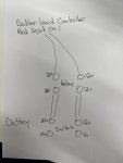
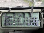
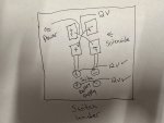
Hey everyone, so my truck has been running perfect until today. I went to start and had no power at all in the cab except for a “Charging System” red light on the dash. My truck has battery disconnect near battery box and it’s always stored in off position. Today I turned the switch as usual and the red light came on the dash, I have never seen anything on the dash light up before without turning the green power switch on dash on. I then turn the green power switch on and Nothing, no power to anything, no buzzer for low air and no crank or clicks from relays. I have charged all battery’s and they at 13v. I have also checked all power connections and seems to be ok except im only getting power to one side of the solenoids after the battery switch. I have attached a drawing for reference. Can someone please help as I have never had a 0 power issue before. I have also attached picture of rely board but my sticker showing what relays do what is missing so I have no idea what to check. Thanks for the help I really needed to use the truck today and am completely stumped by this.

IMG_2596.jpeg
 

Attachments

NDT

Well-known member
Steel Soldiers Supporter
10,187
5,926
113
Location
Camp Wood/LC, TX
Your problem seems to be between the batteries and the disconnect solenoid. Suggest you use your multi meter or test light to see at what connection the voltage drops off. Sometimes there can be corrosion between the cable strands and the connector which is hard to diagnose.
 

GeneralDisorder

Well-known member
Steel Soldiers Supporter
1,524
4,229
113
Location
Portland, OR
In your hand drawn diagram there - it's not positive and negative that you are dealing with - it's +12v and +24v and the negative is the chassis for both. Looks like you are missing the +24v?

Check your battery terminals and cables first.
 

LmtvPR

Member
32
23
8
Location
Puerto Rico
In your hand drawn diagram there - it's not positive and negative that you are dealing with - it's +12v and +24v and the negative is the chassis for both. Looks like you are missing the +24v?

Check your battery terminals and cables first.
I have checked voltage again and provided another diagram for reference. I also let check sit for about 1 1/2 hours with battery switch off then went to check voltage again and had 24v on the far left relay post. i then went into the cab and turned on green switch, heard relays click, had 12v power to dash and attempted to start truck. the truck turned over but was weak then stopped and all power was lost again. I have a feeling its the battery disconnect rely that has gone bad and is not supply consistent 24v power. my employee who used truck last week said he lift lights on with drained the battery and after calling midwest to trouble shoot they said leaving battery on can burn up the rely. Please advise if this all sounds correct as I didn't really want to lay down almost $700 for a new rely.
 

Attachments

Last edited:

Mullaney

Well-known member
Steel Soldiers Supporter
Supporting Vendor
7,433
19,186
113
Location
Charlotte NC
I have checked voltage again and provided another diagram for reference. I also let check sit for about 1 1/2 hours with battery switch off then went to check voltage again and had 24v on the far left relay post. i then went into the cab and turned on green switch, heard relays click, had 12v power to dash and attempted to start truck. the truck turned over but was weak then stopped and all power was lost again. I have a feeling its the battery disconnect rely that has gone bad and is not supply consistent 24v power. my employee who used truck last week said he lift lights on with drained the battery and after calling midwest to trouble shoot they said leaving battery on can burn up the rely. Please advise if this all sounds correct as I didn't really want to lay down almost $700 for a new rely.
.
I would spend Saturday charging batteries. Leave them connected as they are in the battery box. Regular old 12v charger. Positive to Positive and Negative to Negative. LOOK AT THE batteries for the "+" and "-" marks and charge all four. It will take all day to charge all four batteries.

Chances are that the two away from the frame (the 12v in the box) are where the problem is. OR you could meter all four batteries and report back with your measurements.
 

LmtvPR

Member
32
23
8
Location
Puerto Rico
.
I would spend Saturday charging batteries. Leave them connected as they are in the battery box. Regular old 12v charger. Positive to Positive and Negative to Negative. LOOK AT THE batteries for the "+" and "-" marks and charge all four. It will take all day to charge all four batteries.

Chances are that the two away from the frame (the 12v in the box) are where the problem is. OR you could meter all four batteries and report back with your measurements.
Thanks for the suggestion but all batteries were already charged over night with a large multi bank charger I bought from govplanet. volts are at 12.8 on each battery and volts are all over 12v and 24v on all post rely except the far left post as shown in my diagram.
 

LmtvPR

Member
32
23
8
Location
Puerto Rico
People here have jumped the relays permanently. Something to consider for diagnostics.
I did think of that but was worried about doing something incorrectly and damaging more electrical parts. Do you know where I can find more info on how someone did that successfully?
 

GeneralDisorder

Well-known member
Steel Soldiers Supporter
1,524
4,229
113
Location
Portland, OR
You just connect the output from the switch to the output from the disconnect relay.

Do you have the old relay with all the little wires on it? Get the new one that's completely enclosed. Those had problems. Here's the PS Magazine article on this issue:


Mullaney

Well-known member
Steel Soldiers Supporter
Supporting Vendor
7,433
19,186
113
Location
Charlotte NC
You just connect the output from the switch to the output from the disconnect relay.

Do you have the old relay with all the little wires on it? Get the new one that's completely enclosed. Those had problems. Here's the PS Magazine article on this issue:

.
Good Find @GeneralDisorder !!

Just in case, here is a PDF of that article.
 

Attachments

Ronmar

Well-known member
3,329
6,711
113
Location
Port angeles wa
Yep, 12 and 24v measured to ground on those large manual switch and disconnect relay terminals. Remember, voltage is only good when measured good with load applied. A nasty high resistance connection will still pass full voltage until you try and pull current thru it.

That 12V measured on the top left 24v terminal on your last drawing is not good. As mentioned you can jump across that side of the connection on the relay to try and get the 24v seen on the lower terminals on to that upper left terminal. For testing you can jumper with just about anything, as long as you don’t try and crank the engine as the load for the controllers is only a few amps as long as it is not trying to power the grid heater, or crank the engine.

another place for you to test voltages is in the power panel(circled in red in your pic). Those 4 bolt heads are power connection points. Two are 12v and 24v battery, two are 12v and 24v ignition After the K1 and K2 ign relays(under the panel).

you should have good 12 and 24 on those power panel battery bolts if you get it to the top terminals in your drawing, but of course that is tested under load. at full load the voltage difference between batteries and power panel should be less than 3%. The 12 and 24 on the top 2 terminals in your drawing are tied to the wires running to the dash 12 and 24 bolts and the alternator 12 and 24 terminals at the LBCD located between spare tire and air filter. Those terminals are out in the weather and notorious for getting corroded and causing electrical issues, so clean them…

IMG_3639.jpeg
 

LmtvPR

Member
32
23
8
Location
Puerto Rico
Thanks for all the help, today I will be cleaning the terminals on the load box and on Friday ordered a new disconnect relay to update it because my truck had the old style with exposed wires. I will have an update by Wednesday hopefully, Im just waiting on the new relay from Midwest.
 

LmtvPR

Member
32
23
8
Location
Puerto Rico
Hey everyone I am still trying to troubleshoot my issue with absolutely no luck. I have since rebuilt the starter and solenoid, replaced battery disconnect relays and replaced the battery voltage box under spare tire. I can’t for the life of me figure out what happened to my perfectly good truck just from sitting with ignition switch left on.
Today I was checking voltage at alternator and all was good except the black box on top the 28v post had no voltage. I then turned on the ignition switch which gave me the charging light on dash and buzzer from no air. The starter button did nothing and I had no clicks. I then turned off and back on and the power was completely gone so no buzzer and the voltage at alternator was now 12v only and all 24v was gone. I then checked top post “24v” on battery box below spare tire and it was showing 12v which should be 24v.
Any help or ideas would be appreciated I have to get this truck moving ASAP and don’t want to keep buying parts and not finding the problem.
 

Wingnut13

Well-known member
Steel Soldiers Supporter
233
560
93
Location
Strafford, NH
Well from personal experience…… if’n the ground on the battery bank is in the wrong spot you will end up with that problem of 12v where it should be 24v and maybe no voltage where it should be 12v. I think I wrote a post about it too. I have an M1078A1.

I had some of the problems you described. Turned out to be rusted up washers under the battery cables on the main power relay.

I’d say start from The power at the relay and verify proper voltage at each connection between the batteries and the control board in the cab. These trucks aren’t super hard to figure out…..when they are wired right.
 

LmtvPR

Member
32
23
8
Location
Puerto Rico
What is the power relay, The box under the spare tire? The batteries all have proper voltage and I have 12 v and 24 v in the proper locations of the battery disconnect solenoid and relay in the box next to the 4 batteries. What ground is on the battery bank, do you have a picture I can reference. Thanks for the info.
 

Ronmar

Well-known member
3,329
6,711
113
Location
Port angeles wa
In the normal configuration the battery ground terminals are the 2 - terminals farthest from the frame. There shoukd be a cable tgat runs from there to the front of the starter motor, and a ground strap tgat ties from that starter motor ground terminal to the drivers frame rail. And another to a nato plug. That strap is your main vehicle ground. You said you worked on the starter, is that strap to the frame installed correctly?

The 4 battery terminals in the middle of the bank2+,2-) that are all tied together are the 12v. Should have a lead to the rear terminal on the manual disconnect.

The two + terminals closest to.the frame are 24v. Should have one wire to the start solenoid, and one lead to the manual disconnect. And one to a nato plug?
 

LmtvPR

Member
32
23
8
Location
Puerto Rico
In the normal configuration the battery ground terminals are the 2 - terminals farthest from the frame. There shoukd be a cable tgat runs from there to the front of the starter motor, and a ground strap tgat ties from that starter motor ground terminal to the drivers frame rail. That strap is your main vehicle ground.

The 4 battery terminals in the middle of the bank2+,2-) that are all tied together are the 12v.

The two + terminals closest to.the frame are 24v.
Sure wish I had some pics but thanks for the info I will check that out tomorrow. I only know about ground strap from alternator to frame but figured there had to be another ground. I do have 4 batteries connected.
 

LmtvPR

Member
32
23
8
Location
Puerto Rico
In the normal configuration the battery ground terminals are the 2 - terminals farthest from the frame. There shoukd be a cable tgat runs from there to the front of the starter motor, and a ground strap tgat ties from that starter motor ground terminal to the drivers frame rail. And another to a nato plug. That strap is your main vehicle ground. You said you worked on the starter, is that strap to the frame installed correctly?

The 4 battery terminals in the middle of the bank2+,2-) that are all tied together are the 12v. Should have a lead to the rear terminal on the manual disconnect.

The two + terminals closest to.the frame are 24v. Should have one wire to the start solenoid, and one lead to the manual disconnect. And one to a nato plug?
Do you happen to have a wiring diagram from the starter to batteries? I just replaced starter by my employee did the work so I don’t know the wires original locations incase he swapped a wire.
 
Top
AdBlock Detected

We get it, advertisements are annoying!

Sure, ad-blocking software does a great job at blocking ads, but it also blocks useful features of our website like our supporting vendors. Their ads help keep Steel Soldiers going. Please consider disabling your ad blockers for the site. Thanks!

I've Disabled AdBlock
No Thanks