• Steel Soldiers now has a few new forums, read more about it at: New Munitions Forums!

  • Microsoft MSN, Live, Hotmail, Outlook email users may not be receiving emails. We are working to resolve this issue. Please add support@steelsoldiers.com to your trusted contacts.

PCB Engine Harness Connector Replacement

Dude82

New member
13
10
3
Location
Michigan
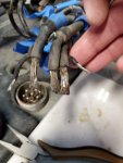
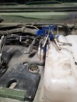
Thanks to help from other posts, learning my way through the TMs. Root causing a wait light issue, broke the engine side connector of the PCB due to corrosion. Removed the old one, prepping to solder new one. The "D" "E" "F" wires are the thick gauge - glow plugs, power stud, and ground strap - wires in the middle of the connector. After stripping, there appears to be some residual insulation or something? Was thinking I'd try to burn it off? Just want to ensure I get a good connection with the new connector....thoughts? Knowledge of what it is?
 

Attachments

springer1981

Well-known member
844
1,150
93
Location
Maine
FYI, I have no personal experience with the connector you are talking about but I have done LOTS of connectors and soldering. First, did the original connector have soldered connections? I ask because every connector on my HMMWV has crimp connections and not soldered. Whatever is on it can probably be lightly scrapped off using razor knife or exacto. Scrape away from you with the edge perpendicular to the wire so it is not cutting into it.

More importantly, back to crimp vs solder connection. Solder is not great or even good with high current connections because heat from the current can melt it. A crimp is a physical clamping of the wire that prevents the high current issue. Think battery cables for example, never soldered always crimped.

If you do solder it then scrapping as suggested will also expose some of the copper in the wire. That wire is coated and why it is silver in color. The copper exposed will allow the flux to better do its job. The flux and heat allows the solder to get under most types of oxidation and left over insulation or rubber in this case. I wouldn't burn it off but I also wouldn't solder it either.
 
  • Like
Reactions: OBX

Dude82

New member
13
10
3
Location
Michigan
FYI, I have no personal experience with the connector you are talking about but I have done LOTS of connectors and soldering. First, did the original connector have soldered connections? ...
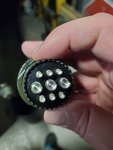
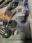
Appreciate the reply. Funny enough, I was hoping for a crimped connection. See pics below, but new connector has solder cups, and looking at old connections they were soldered as well. You can kind of make it out in the photo. For what it's worth, it's the connector next to the windshield washer reservoir, coming from engine. My original hope was to reuse as much of the wire as possible because there isnt much extra. But I did not want to mess with de-soldering, and if it was plug and play - corrosion changed that plan.

Out of curiosity though, seeing at it was soldered before, with what you said above, any guesses on why they might have did it for this?
 

Attachments

  • Like
Reactions: OBX

Milcommoguy

Well-known member
Supporting Vendor
1,713
2,279
113
Location
Rosamond, CA
Appreciate the reply. Funny enough, I was hoping for a crimped connection. See pics below, but new connector has solder cups, and looking at old connections they were soldered as well. You can kind of make it out in the photo. For what it's worth, it's the connector next to the windshield washer reservoir, coming from engine. My original hope was to reuse as much of the wire as possible because there isnt much extra. But I did not want to mess with de-soldering, and if it was plug and play - corrosion changed that plan.

Out of curiosity though, seeing at it was soldered before, with what you said above, any guesses on why they might have did it for this?
You might be able to pull back some slack like an inch or two by removing a clamp along the windshield. My concern is tinning the conductors if the corrosion as found it way between the strands.. Cleaning and good rosin flux (not plumber or acid) to pre-tin the wire ends / tip only. About a 1/4 inch. Don't need solder wicking up thru the area shown (cut back). Solder only what is in the connector "solder cup" Slip a little shrink sleeve 1/2 or so on before soldering, keeping it back and away from the heat socking up the wire. Those pins and 8ga wire will require a LOT of heat. They will suck the fire out of anything smaller than smaller than 125 watts. Big iron and big tip, get it hot, flow the soldered quick to the pin and wire, get out and don't MOVE. Might need a third hand or clamp it down from to work it. NO COLD SOLDER JOINTS.

And that's the hot tip of the day IMO, CAMO
 
Last edited:

springer1981

Well-known member
844
1,150
93
Location
Maine
The resolution isn't great but these look like crimp pins to me. First you typically can't remove solder cup pins. Second, the pin is right to the wire insulation. Third, they don't have the side missing for soldering. Those pins all look good, too bad you cut them off already, I bet you just needed the right connector.


Retiredwarhorses

Well-known member
Steel Soldiers Supporter
4,414
4,207
113
Location
Brentwood, Calif
Thanks to help from other posts, learning my way through the TMs. Root causing a wait light issue, broke the engine side connector of the PCB due to corrosion. Removed the old one, prepping to solder new one. The "D" "E" "F" wires are the thick gauge - glow plugs, power stud, and ground strap - wires in the middle of the connector. After stripping, there appears to be some residual insulation or something? Was thinking I'd try to burn it off? Just want to ensure I get a good connection with the new connector....thoughts? Knowledge of what it is?
you want me to just send you a complete replacement cut off from a harness? Than all you need to do is butt splice them together.
 

springer1981

Well-known member
844
1,150
93
Location
Maine
you want me to just send you a complete replacement cut off from a harness? Than all you need to do is butt splice them together.
Dude, you should absolutely take him up on this offer. Then use good quality Crimp type heat shrink butt connectors. Then use some black heat shrink tubing over the butt connectors. I'll send you some black heat shrink tubing if you need it.
 

Dude82

New member
13
10
3
Location
Michigan
Dude, you should absolutely take him up on this offer. Then use good quality Crimp type heat shrink butt connectors. Then use some black heat shrink tubing over the butt connectors. I'll send you some black heat shrink tubing if you need it.
Appreciate your responses and advice! I should be set on heat shrink. Have some marine shops nearby that I can stop at for good butt connectors too.
 
Top
AdBlock Detected

We get it, advertisements are annoying!

Sure, ad-blocking software does a great job at blocking ads, but it also blocks useful features of our website like our supporting vendors. Their ads help keep Steel Soldiers going. Please consider disabling your ad blockers for the site. Thanks!

I've Disabled AdBlock
No Thanks