• Steel Soldiers now has a few new forums, read more about it at: New Munitions Forums!

  • Microsoft MSN, Live, Hotmail, Outlook email users may not be receiving emails. We are working to resolve this issue. Please add support@steelsoldiers.com to your trusted contacts.

Picked up 6 MEP-802A gensets and will be documenting making them all runners here

pclausen

Well-known member
Steel Soldiers Supporter
452
281
63
Location
Afton, VA
Since I have a pair of those copper washers left over that dops in before the injectors, I'm going to pull the injectors on the spare unit in the morning, just to make sure they go with that unit. If the spare set DOES have those copper washers, then I forgot to install them on this unit that won't start, and that would certainly explain the issue.

Even if this set that I can't get started does have washers, I'll probably still pull the injectors and pull out the washers and annealing them like I did the 2006 I have been working on. Never did that on any of the other sets I worked on, but figured that would be one thing to do to help if this is a compression issue.

If it is getting fuel, compression is about the only thing left that could keep it from firing I would think.

I saw a couple of old threads about an adapter for testing compression on these engines, but I don't believe anyone is actually selling any at this point?
 

kloppk

Well-known member
Steel Soldiers Supporter
2,168
3,610
113
Location
Pepperell, Massachusetts
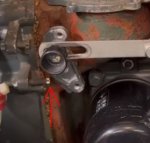
In the first cranking video showing the fuel solenoid I spotted an issue. The fuel solenoid is not causing the arm on the side of the governor to fully rotate to the RUN position. It should rotate and contact the head of the lower adjustment screw. Failure to do so will cause the fuel rack to not move fully to the RUN position. Thus the IP's won't be opened.

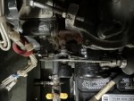
Here is a pic from your cranking video showing the arm not against the adjustment screw.
Fuel Start.JPG

Next time see if you can rotate the arm by hand so it touch's the lower screw head while cranking.
 

jamawieb

Well-known member
1,435
557
113
Location
Ripley/TN
In the first cranking video showing the fuel solenoid I spotted an issue. The fuel solenoid is not causing the arm on the side of the governor to fully rotate to the RUN position. It should rotate and contact the head of the lower adjustment screw. Failure to do so will cause the fuel rack to not move fully to the RUN position. Thus the IP's won't be opened.

Here is a pic from your cranking video showing the arm not against the adjustment screw.
View attachment 858751

Next time see if you can rotate the arm by hand so it touch's the lower screw head while cranking.
I agree with Kloppk, something is going on with the arm. Watching the 1st video the arm is not moving freely like it should. Soon as the solenoid retracts the arm should move smoothly and fast. In you video its not moving smoothly, it acts like its catching on something. Need to check the fuel rack too.
 

pclausen

Well-known member
Steel Soldiers Supporter
452
281
63
Location
Afton, VA
I thought that looked a little off, which is why I videoed it. Anyway, holding the arm all the way in the RUN position did nothing to get it started.

I'll return to the arm in a moment. So I went down to the shop to pop the injectors on the 802 with the cracked piston, only to realize I never had the injectors out on the head, I just remove the entire head to see what was going on with the pistons.

So I popped the injectors on the 2007 unit that cranks but won't fire, and sure enough, the copper washers were missing! So I heated them cherry hot, let them cool, and re-installed with the washers this time. :)

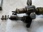
Still no joy with or without holding the arm in the run position. So I pulled both IPs. They both seem to be fine, the arms move very smoothly on both of them.

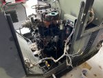
IMG_0442.JPG

The front one (top) had 4 clear and a green shim. The rear (bottom) has 4 clears, so very close.

Anyway, the arm still doesn't move really smooth with the IPs removed. It starts out easy, but about 3/4 of the way through, there is a little resistance. Just enough that the spring does not pull it all the way to the RUN position on its own. The 2006 model I'm working on sitting next to it, is buttery smooth by comparison. On the 2006 unit, I can put my pinky on the lower portion of the arm and move it effortlessly from STOP to RUN. That is definitely not the case on the 2007 unit. It takes a lot of effort to do that with my pinky alone. Use my whole hand, no problem.

I guess my next move is to pop the timing cover and pull the whole rack out to have a closer look at it? (sigh...)
 

Light in the Dark

Well-known member
Steel Soldiers Supporter
3,860
6,074
113
Location
MA
I have (3) 802s here right now that all have fuel rack related concerns (either not moving correctly, missing parts, etc). I'm right there with you on the annoying factor.
 

pclausen

Well-known member
Steel Soldiers Supporter
452
281
63
Location
Afton, VA
Got the timing cover off. It involved the following:

1. Drain coolant & oil
2. Remove both fan shrouds
3. Loosen alternator & remove fan belt
4. Remove radiator
5. Remove fan
6. Remove crank pulley
7. Remove timing cover

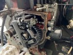
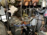
View with cover removed:

IMG_0446.JPG

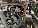
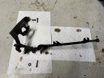
Pump rack moves in and out very smoothly, so that's not the issue. The arm shaft itself is what is a little tight. Some pics:

IMG_0444.JPG

I did take off the spring that pulls the rack towards the IPs for checking that it was smooth. So that spring is not the issue, it was just not on when I took the pics.

IMG_0445.JPG

Everything else looks good and pretty much how I remember it from assembling it 6 years ago.

Any recommendations on how to lubricate the shaft so that it will rotate/spin more easily? Should I attempt to remove the nut on the inside and try to pull the shaft/arm out, or just spray some penetrating oil where the shaft enters the block?
 
Last edited:

pclausen

Well-known member
Steel Soldiers Supporter
452
281
63
Location
Afton, VA
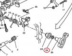
I tried some PB Blaster. That did nothing. Looking at the parts diagram:

lever.jpg

I suspect the preformed packing (24) is what makes the lever a little sticky. I did not replace it when I had everything apart. I'm not even sure I had the arm disassembled at all.
 

pclausen

Well-known member
Steel Soldiers Supporter
452
281
63
Location
Afton, VA
I went and pulled that arm from the spare unit (which was nice and smooth) and compared it to the "sticky" one:

IMG_0449.JPG

Sticky on top, smooth on bottom. So the issue was that the O-ring used was too large on the sticky one. Fortunately I had a spare that was the correct size, so I swapped them out.

Removing the fuel rack is pretty straight forward. Just undo 2 pins and the whole thing slides out:

IMG_0450.JPG

I used the method of holding the rack on the stop position when installing each IP:

IMG_0451.JPG

So after all that, the action of the arm is now smooth like it should be:


However, the original problem remains. It won't fire. I guess I'll go pick up some starting fluid to see if I have compression or not, and if there's some other issue I'm not aware of yet.
 

DieselAddict

Well-known member
Steel Soldiers Supporter
2,541
2,090
113
Location
Efland, NC
I use a little WD40 to get one to light off. Ether is fine too but I think wd40 is a little more gentle. Even if it doesn't start you'll see when it gets to the cylinders in the exhaust.
 

pclausen

Well-known member
Steel Soldiers Supporter
452
281
63
Location
Afton, VA
Picked up some starter fluid and gave it a few shots. Nothing at all. Tried a few more, and its completely dead.

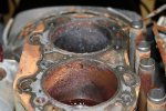
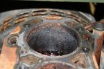
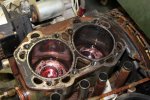
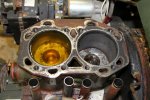
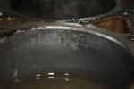
So no compression. Keep in mind the 2007 started out looking like this back in June of 2014 when I first tore into it:

802A-2007-6-22-03.JPG

802A-2007-6-22-04.JPG

And after sitting in Evapo-Rust for a day, it looked like this:

802A-2007-6-23-1.JPG

After 2 days:

802A-2007-6-24-01.JPG

802A-2007-6-24-02.JPG

After that my picture trail goes dry. But I would have put the rebuild head on it a month or so later, and it wouldn't start, and it has been sitting ever since until I picked it back up again last week.

So I think what this 2007 needs is:

1. Pull the head off
2. Pull out the pistons
3. Hone the bores
4. Inspect / Replace the rings

Try again.
 
Last edited:

Ray70

Well-known member
Steel Soldiers Supporter
2,633
6,060
113
Location
West greenwich/RI
I'd agree with your game plan.
When you crank the 2007 over, how does it sound? does it spin abnormally fast, without strong compression pulses?
I assume you already have a cylinder hone, but if not get yourself a Lisle 15000 micrometer head hone.
I've successfully honed these motors up to .020" oversize to repair rust pits and even one with a groove from a broken wrist pin clip.
Takes a while, but makes a nice round bore, something a ball hone and 3 finger hones won't do.
If things are really bad in that motor you can easily take it to .010" over and get pistons from Mayi, if need be...
 

pclausen

Well-known member
Steel Soldiers Supporter
452
281
63
Location
Afton, VA
It does sound like it has SOME compression. Here's a video of it cranking from yesterday:


I have a regular 3 finger hone, but that Lisle 15000 does look pretty cool. I do have 2 sets of .020" rings that I can file down as needed.

I suspect the 2006 will probably need the same treatment, but I'll find out next week when the fuel filter parts come in.
 
Last edited:

Guyfang

Moderator
Staff member
Moderator
16,924
24,543
113
Location
Burgkunstadt, Germany
I am not going to say this is the problem. But to my eye, the arm and knob still do not move correctly. So look at attachment Linkage. Item #4. Is a nut with a "neck", if you will, that fits in the slot on the long arm. Without that neck, it will not slide right. And it should slide freely in that slot.

Then look at Linkage adj. I do not think yours, is set like that one in the attachment.

Then Engine stop screw adj. Don't know if I sent you this before, and as the thread is a million pages long, am not going to look. If not, check that its in spec. If I sent it, then off to the great data Friedhof in the sky.


Attachments

pclausen

Well-known member
Steel Soldiers Supporter
452
281
63
Location
Afton, VA
Thanks for the linkage pics. Mine is a little different in that I don't have the nut with the collar. However, I'm using 2 nuts and 2 washers to accomplish the same thing:

IMG_0460.JPG

The flat piece with the long slot attached to the solenoid slides freely as one nut is jammed against the lever arm, and the other nut is jammed against the head of the bolt. There are a few millimeters of play in the sandwich made up of the 2 washers and the flat piece with the slot.

There is some play in the shaft the lever is attached to, maybe a millimeter or so side to side at the end of the arm (not the shaft itself) I did go through the procedure of setting the timing of the IPs per the pages you sent. They were pretty much spot on, but I redid the calibration again, just to rule that out as the issue.

Same thing as before when cranking. I get diesel mist out the exhaust, but not ignition. When I put my hand over the exhaust, it seems I get both pressure and suction, but I guess that is normal since there is no firing? Sure wish there was a way to do a compression test before pulling the head back off, but the lack of ignition with the starting fluing was probably pretty telling of the issue.

I don't suppose you can "flood" a diesel engine? i.e. the issue with the starting fluid not working could not be that there is too much diesel mist in the cylinders, could it?
 

Guyfang

Moderator
Staff member
Moderator
16,924
24,543
113
Location
Burgkunstadt, Germany
Then its time to check compression. If you can not find or make a compression gauge, then do the Vacuum test. This engine is supposed to run with a vacuum on the crankcase. So if you have bad rings, that compression has to go south. Crankcase. If there is an over pressure on the crankcase, then you will see it on the vacuum test.

3-5. CRANKCASE VACUUM.
3-5.1. General. The value depends to some extent on the type and size of air cleaner installed on tie engine.
Regardless of type air cleaner used, vacuum with a clean air cleaner must not be less than a minimum of 0.79 in. (20
mm) water gage (WG). The vacuum is measured with a manometer at the lubricating oil dipstick hole with the engine
running. In engines in good condition vacuum increases slightly with engine speed but not proportionally. A fluctuating
vacuum may indicate faulty oil seals, valves, or piston blow-by troubles. Crankcase pressure can cause serious oil leaks
and often occurs in engines which need overhauling.
3-5.2. Measure Vacuum.
NOTE
Average vacuum should be 1.37 in. (34.8 mm) WG. Minimum allowed is 0.79 in. (20 mm) WG.
a. Remove lubricating oil dipstick.
b. If water manometer is available, connect one end of a 0.374 in. (9.5 mm) OD plastic tube to a water manometer.
Insert other end of tube into dipstick hole. Refer to FIGURE 3-1.

1644831359393.png
 

pclausen

Well-known member
Steel Soldiers Supporter
452
281
63
Location
Afton, VA
So I cobbled this manometer together:

IMG_0461.JPG

I filled with water to the 6" mark:

IMG_0462.JPG

I then dead cranked the engine and all the water blew out the end of the tube. So lots of pressure in the crank case it would seem.

I guess that means its time to pull the pistons and have a look at the rings, honing the bores, etc as mentioned above, right? The head was freshly (well back in 2014 but never used) rebuild, so I'm sure it is fine.
 
Last edited:

Zed254

Well-known member
866
467
63
Location
S. Hampton Roads, VA

I did same thing when I set up a manometer for my 802: blew all the water out of the tubing. I then set up an air chamber to absorb the air pulses and found that my oil sump vacuum was within specification.
 

pclausen

Well-known member
Steel Soldiers Supporter
452
281
63
Location
Afton, VA
Well, I added a 2.5 quart "can" in my loop:

IMG_0463.JPG

That made for an even more impressive show. At first I though the lid was going to pop off given how it domed up, but a split seconds later, I just got a jet of water coming out the tube hitting the ceiling of my garage.

So yeah, rings / cylinder walls I'm guessing.
 

pclausen

Well-known member
Steel Soldiers Supporter
452
281
63
Location
Afton, VA
The parts for the secondary fuel filter finally showed up today, so I was able to go back to working on the 2006 unit. I know I need to pop the head on the 2007, but I'll save that work for a rainy day. :)

After getting the filter installed, I tried priming, but the fuel pump (old square style), just made a faint humming sound. Undid the suction side and tried blowing into the line going to the tank. Was completely clogged. Using compressed air, I cleared the blockage. While I had the line off, I dripped a little diesel into the inlet of the pump. It still just gave a faint hum. Tapped on the side of it, and little by little it got louder until all of a sudden it started pumping.

I then reconnected the line from the tank and let it run for 5+ minutes to get the fuel circulate real good. I then tried to crank it. Nothing. I heard a click coming from the control box, but the main solenoid on the starter never engaged. Put a voltmeter on the solenoid and it never goes to 24V when trying to crank. Same deal using the dead crank switch.

So I guess the relay that controls the starter solenoid needs to have its contacts cleaned? Need to study the starter circuit diagram to diagnose further.

Also also got in some fuel senders today. The 5.5" ones. Am I correct that it doesn't matter how I connect the red and black wires since it is just a resistor and the whole thing is floating being a plastic fuel tank? Or should I slip the one eyelet under one of the screws and tie the black wire from the sensor to it?
 
Top
AdBlock Detected

We get it, advertisements are annoying!

Sure, ad-blocking software does a great job at blocking ads, but it also blocks useful features of our website like our supporting vendors. Their ads help keep Steel Soldiers going. Please consider disabling your ad blockers for the site. Thanks!

I've Disabled AdBlock
No Thanks