• Steel Soldiers now has a few new forums, read more about it at: New Munitions Forums!

  • Microsoft MSN, Live, Hotmail, Outlook email users may not be receiving emails. We are working to resolve this issue. Please add support@steelsoldiers.com to your trusted contacts.

Picked up 6 MEP-802A gensets and will be documenting making them all runners here

Light in the Dark

Well-known member
Steel Soldiers Supporter
3,829
5,940
113
Location
MA
Depending on your acquisition price, its either a real nice parts machine now for your other sets... or worth tracking down a stator based on market values. You are putting more work into these things than I would, cheers to you.
 

pclausen

Well-known member
Steel Soldiers Supporter
452
281
63
Location
Afton, VA
I already have a parts machine, and I just tested the windings on the stator on it, and they are all good. So I'll swap the stator from it over onto this one.

The thing that sucks is that I just put this machine together and had the stator separated from the engine and I let it go because the resistance at the time was about 0.3 ohm, not the 0.1 ohm it is reading now.
 

Guyfang

Moderator
Staff member
Moderator
16,766
24,079
113
Location
Burgkunstadt, Germany
If you are going to do the swap, then I would tell you to check EVERY OTHER connection on the AC output side. Do not ASSUME everything is hunky dorry. KNOW it is. With the main gen out, there really is not all that much to look at.

If you do start work on another gen set, I would advise starting a thread for that gen set. 29 pages, 564 posts.
 

pclausen

Well-known member
Steel Soldiers Supporter
452
281
63
Location
Afton, VA
Thanks for the heads up Light on the stators. Once I get down to the last unit, I'll weigh getting what I need to make it a runner, vs. parting it out, or just keeping it for the 2 units I plan to keep long time (a 802 and a 803).

Good idea Guy about starting a separate thread for the next one I tear into!

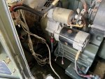
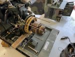
So I did get the rear section removed from the set with the bad stator winding. All wires removed on the starter side:

IMG_0576.JPG

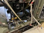
All wires (and fuel lines), removed from the oil filter side:

IMG_0578.JPG

Had to remove the door sill as well in order to slip the rigid fuel line above the oil drain to facilitate sliding the whole rear section off.

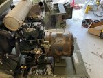
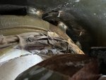
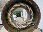
Stator exposed:

IMG_0580.JPG

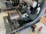
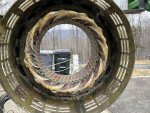
Other side:

IMG_0581.JPG

Took about an hour to remove the rear section, start to finish.
 

Guyfang

Moderator
Staff member
Moderator
16,766
24,079
113
Location
Burgkunstadt, Germany
Thanks for the heads up Light on the stators. Once I get down to the last unit, I'll weigh getting what I need to make it a runner, vs. parting it out, or just keeping it for the 2 units I plan to keep long time (a 802 and a 803).

Good idea Guy about starting a separate thread for the next one I tear into!

So I did get the rear section removed from the set with the bad stator winding. All wires removed on the starter side:

View attachment 859970

All wires (and fuel lines), removed from the oil filter side:

View attachment 859971

Had to remove the door sill as well in order to slip the rigid fuel line above the oil drain to facilitate sliding the whole rear section off.

Stator exposed:

View attachment 859972

Other side:

View attachment 859973

Took about an hour to remove the rear section, start to finish.
When you do it several times, you quickly find the short cuts and it takes really not long at all to get at the main gen.

I think what you are seeing could be what happens when the A1 is bad in the over volt way. Hence the Quad Mod.
 

pclausen

Well-known member
Steel Soldiers Supporter
452
281
63
Location
Afton, VA
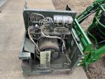
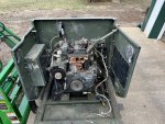
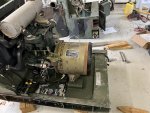
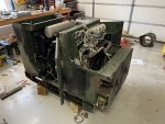
Got the spare 802 pulled out of storage. Parts have already been picked from it.

IMG_0587.JPG

IMG_0588.JPG

It has the cleanest harness of all the units I have though:

IMG_0589.JPG

Got the rear section removed along with the stator:

IMG_0591.JPG

Only took about 20 minutes on this unit. Of course it helped that the front section had already been removed.

Stator was very dusty inside:

IMG_0590.JPG

The end housing was cracked in a couple of places, so I'm going to transfer over my existing one.

IMG_0592.JPG

After a lot of compressed air and wiping down with a moist rag, it looks halfway decent:

IMG_0593.JPG

IMG_0594.JPG

Nothing crispy and I get 0.5 Ohm across all 6 windings and 1.0 Ohm on pins 3-4 on P5 (Q and Q2 leads), so I think this stator is a winner.
 

pclausen

Well-known member
Steel Soldiers Supporter
452
281
63
Location
Afton, VA
Yep, I put a new bearing on when I put it together the first time a few weeks ago.

Got the replacement stator installed with the existing rear bell support that is not cracked (and the new bearing).

IMG_0595.JPG

Rear end almost slid back on all the way:

IMG_0596.JPG

Just making sure the wires and fuel lines got in the right place before sliding it the rest of the way back on.

So I got everything re-wired and fired it back up without the 12 stator leaded connected to TB3. No issues. Got about 30VAC coming out of each winding pair.

Proceeded to connect the stator leads to TB3 and fired it up again. Was getting low readings unless holding S1 in the START position. Checked the Quad Mod fuse, it was blown. Replaced it and now I was getting readings, but they are not quite right.

I'm getting:

A1 to C1 240 VAC
A1 to B1 70 VAC
B1 to C1 65 VAC

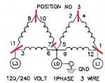
I believe the reason for this is that S8 is not making all the connections that it should in position 3.

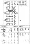
From post #557 on the previous page, I noted that I was not seeing connectivity between the following (red lines) with the S8 switch in position 3:

1phase3wire.jpg

Is S8 sealed, or will it help to spray it with Contract Cleaner and working the switch a bunch of times?

Or should I just go ahead and swap out S8 from the spare set?
 

Guyfang

Moderator
Staff member
Moderator
16,766
24,079
113
Location
Burgkunstadt, Germany
This is what I wrote in post #564

If you are going to do the swap, then I would tell you to check EVERY OTHER connection on the AC output side. Do not ASSUME everything is hunky dorry. KNOW it is. With the main gen out, there really is not all that much to look at.
 

pclausen

Well-known member
Steel Soldiers Supporter
452
281
63
Location
Afton, VA
I hear you Guy and I visually verified that all the jumpers and wires match what I have on the set sitting next to this one.

But I'll remove all wires from S8 and go through the settings to see why I'm not observing the continuity I should according to the schedule.

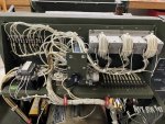
View of the AC switching section with the control box removed:

IMG_0602.JPG

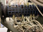
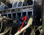
TB3 facing side of S8:

IMG_0600.JPG

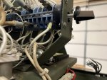
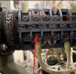
K1 side of S8:

IMG_0601.JPG

I think S8 is messed up, but I'll verify that by comparing to this chart:

S8 switch schedule.jpg
 

pclausen

Well-known member
Steel Soldiers Supporter
452
281
63
Location
Afton, VA
Ok, I must not be reading the schedule right, or both this 802 and the one sitting next to it (the one with no/low compression that won't fire).

When I put an ohm meter between 7-8 or 9-10 or 13-14 I show an open circuit with S8 in position 3 on BOTH sets.

What are the odds that both have failed S8 switches?

Are they serviceable? Does it come apart like a really tall sandwich?
 

Guyfang

Moderator
Staff member
Moderator
16,766
24,079
113
Location
Burgkunstadt, Germany
Odds are slim. Yes it comes apart. You need to know, that its not a user friendly thing to take it apart AND get it back together. Several folks here have done it, with success.
 

pclausen

Well-known member
Steel Soldiers Supporter
452
281
63
Location
Afton, VA
Thanks Kurt. Yep, that's definitely where I was probing. Tomorrow I'm going to probe the spare unit to see what kind of readings I get on the S8 switch in it. Hopefully it will actually show the proper readings.

On the unit I'm working on, the readings between 7 & 8 are:

S8 PositionReading
1Open
21 MOhm
34 MOhm

I suppose one option would be to permanently jump this unit to position 3 since I suspect almost everyone would use it in 120/240 V 1 Phase operation anyway.
 

pclausen

Well-known member
Steel Soldiers Supporter
452
281
63
Location
Afton, VA
I tested the S8 switch on the spare set, and it also fails to show continuity between terminals 7 & 8 in position 3. So 3 failed S8 switches on a sets. What are the odds....

Here's a quick video I made of the S8 switch on the set I'm working on:


I start out with a short (yellow test leads) between terminals 7 & 8. As you can see, I show continuity as I should.

I then remove the test lead see an open circuit with S8 in position 1.

Moving to position 2, I show about 800 KOhm.

In position 3 I'm all over the place ranging from about 1 MOhm to over 3 MOhm.

So it looks to me like I need to take the switch apart to clean the contacts? Swapping in the S8 switch from the spare set would do me no good apparently since it is having the same issue (as is the set with low compression).
 

jamawieb

Well-known member
1,437
556
113
Location
Ripley/TN
In all my years I've only seen one s8 switch fail. Most of the time you need to clean them with electrical cleaner to get them to properly work. Sand and grime can get in between the contacts and it won't make a good contact.
 
Top
AdBlock Detected

We get it, advertisements are annoying!

Sure, ad-blocking software does a great job at blocking ads, but it also blocks useful features of our website like our supporting vendors. Their ads help keep Steel Soldiers going. Please consider disabling your ad blockers for the site. Thanks!

I've Disabled AdBlock
No Thanks