• Steel Soldiers now has a few new forums, read more about it at: New Munitions Forums!

  • Microsoft MSN, Live, Hotmail, Outlook email users may not be receiving emails. We are working to resolve this issue. Please add support@steelsoldiers.com to your trusted contacts.


Picture of m1079 with box removed.

ramdough

Well-known member
1,554
1,727
113
Location
Austin, Texas
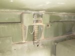
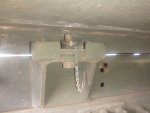
Anyone have a picture of an M1079 with the box removed? Is the box mounted to the lower frame or is there an upper frame? If it uses an upper frame, is there any cross bars up there?

Anyone have dimensions or drawings for the mounts?

Looking at using a similar mount scheme on an m1083.

Thanks!


Sent from my iPhone using Tapatalk
 

ramdough

Well-known member
1,554
1,727
113
Location
Austin, Texas
Pictures of how the pieces are fabricated might help too.

Thanks!

Tagging in [mention]Keith Knight [/mention] [mention]Third From Texas [/mention] [mention]fuzzytoaster [/mention]


Sent from my iPhone using Tapatalk
 

GeneralDisorder

Well-known member
Steel Soldiers Supporter
1,436
4,032
113
Location
Portland, OR
I can take some pics for you.

There are no cross-bars.

It has an upper frame with the mounts for the box. It's pretty ingenious actually. The front mount is "captured" inside a box so it can rise up and down. It is affixed with about an 8" piece of all-thread that has a spring under the body side of the mount to allow the front of the box to tilt up with frame flex. The rear is loosely bolted. Both the front and rear have a slice of rubber between the box and the upper frame. Both are left LOOSE and have castellated nuts with ringed clevis pins to keep them from spinning off. The idea is that frame flex will not result in stresses on the box. It's pretty simple and ingenious actually.

Rick
 

coachgeo

Well-known member
4,929
3,314
113
Location
North of Cincy OH
I can take some pics for you.

There are no cross-bars.

It has an upper frame with the mounts for the box. It's pretty ingenious actually. The front mount is "captured" inside a box so it can rise up and down. It is affixed with about an 8" piece of all-thread that has a spring under the body side of the mount to allow the front of the box to tilt up with frame flex. The rear is loosely bolted. Both the front and rear have a slice of rubber between the box and the upper frame. Both are left LOOSE and have castellated nuts with ringed clevis pins to keep them from spinning off. The idea is that frame flex will not result in stresses on the box. It's pretty simple and ingenious actually.

Rick
yep what he says.

it is called a "captured spring system" and its being used more often in the Overland build industry if the truck frame is rather rigid. As in typical commercial truck chassis design which does not twist frame up as much compared to say a Unimog with a rather flexy frame ....so much flex even transmission may be on a pivoting mount. The rubber cushions that sit in the box in a box/cups on the M1079 locating system, are actually different thickness in front compared to back and they are slightly wedged too if I recall right.
 

Attachments

Ronmar

Well-known member
3,184
6,477
113
Location
Port angeles wa
you mean something like this?

there are upper crossmembers as the upper subframe is a welded structure.

If I recall correctly the tape measure was hooked at the rear end of the upper frame.

all the LMTV’s have 2 frame rails/upper subframe. the upper frame is configured for the specific application(m1078 bed, M1079 box, ect. There is a designation for an M1080, which I believe has an unmodified upper subframe for some other application(rocket launcher, missile battery, mobile control tower ect)…

89A293D4-BF67-4D27-AF84-87D602AB45C3.jpeg


3494262F-B982-491D-9379-08870E5A2ADB.jpeg7C6963C2-4B07-4C24-B754-E5CDF1F2B708.jpeg1F3ECBC4-8848-4B9F-A257-CC9200DFFE30.jpegF5091D2D-98E9-43F4-B2D0-15F5959A5DFE.jpeg2ECCEED3-C998-437E-8157-1F17CED68BB7.jpeg873D711C-B52C-43EB-BC4F-B2E0FE7D3FDE.jpeg
 
Last edited:

ramdough

Well-known member
1,554
1,727
113
Location
Austin, Texas
you mean something like this?

there are upper crossmembers as the upper subframe is a welded structure.

If I recall correctly the tape measure was hooked at the rear end of the upper frame.

all the LMTV’s have 2 frame rails/upper subframe. the upper frame is configured for the specific application(m1078 bed, M1079 box, ect. There is a designation for an M1080, which I believe has an unmodified upper subframe for some other application(rocket launcher, missile battery, mobile control tower ect)…

View attachment 852109


View attachment 852101View attachment 852102View attachment 852103View attachment 852104View attachment 852105View attachment 852106
Yes, exactly like that!

So it looks like there are two cross bars on the frame near each mount. I am assuming this is only to keep the frames from rolling from the moment they see when the weight is on them.

Ron, do you have the same info on the upper mounts as well?


Sent from my iPhone using Tapatalk
 

ramdough

Well-known member
1,554
1,727
113
Location
Austin, Texas
Also, do you have the steel thicknesses?

I may copy part of the design…..I may make the pickets deeper since I will have much more travel on the rear ones.


Sent from my iPhone using Tapatalk
 

coachgeo

Well-known member
4,929
3,314
113
Location
North of Cincy OH
Also, do you have the steel thicknesses?

I may copy part of the design…..I may make the pickets deeper since I will have much more travel on the rear ones.


Sent from my iPhone using Tapatalk
pockets are not typical. Infact IMHO its pretty genius.. had never seen the used with captured springs before..... but that said...... not sure deeper ones will help. They only assist box alignment via the side still in the pockets. Deeper pockets wont allow for movement when you need it IMHO. Feel like deeper will cause bind in the pocket on the side where truck chassis flex needs to move away from the box's chassis.

Have seen captured spring sets up where they incorporate a sliding arm(s) in a few places on the sides.. it attaches to the box chassis.....and is free to slide on the truck chassis. these are to provide/assist box locating by helping hold box in place on the side where chassis flex has allowed separation between box and truck two different chassis. The length of the arms are long enough to allow arm to still be up aganst the truck chassis even when flex separated the two chassis. The nice ones had a greaseable poly plastic mounted on chassis(or was it arm??) for arm to slide along chassis smoothly.

now if your going to have a good bit more truck chassis flex than what our trucks do now... IMHO you need to go to a different system all together. (box sub chassis mounted on pivots.)
 
Last edited:

Ronmar

Well-known member
3,184
6,477
113
Location
Port angeles wa
Also, do you have the steel thicknesses?

I may copy part of the design…..I may make the pickets deeper since I will have much more travel on the rear ones.


Sent from my iPhone using Tapatalk
The bracket/pockets are 3/8” plate.

in addition to the two channel crossmembers near the pockets there is a box structure that houses the rear crane/helo lift arms, which is built into/thru that upper subframe….

You can see it in the upper left corner of the first picture, the front mudflaps for the rear tires are attached to it…
 

Ronmar

Well-known member
3,184
6,477
113
Location
Port angeles wa
yep what he says.

it is called a "captured spring system" and its being used more often in the Overland build industry if the truck frame is rather rigid. As in typical commercial truck chassis design which does not twist frame up as much compared to say a Unimog with a rather flexy frame ....so much flex even transmission may be on a pivoting mount. The rubber cushions that sit in the box in a box/cups on the M1079 locating system, are actually different thickness in front compared to back and they are slightly wedged too if I recall right.
my 1079 chassis still had the rubber spacers in the pockets and they were all the same size/thickness, about 1/2” if I reca…
 

coachgeo

Well-known member
4,929
3,314
113
Location
North of Cincy OH
my 1079 chassis still had the rubber spacers in the pockets and they were all the same size/thickness, about 1/2” if I reca…
good to know... that is telling. Might sorta identify the stress forces in them ending up slightly different once squashed out. Assuming that is why size difference Alex? reported. He found they were wedged? and different sized for front and rear pockets.. I'll try to find the info. Don't recall if his were new or used/abused.

Update:
orrrr... their is a difference in the pockets slightly between A0 and A1. further discussion down below seems to point to that.
 
Last edited:

GeneralDisorder

Well-known member
Steel Soldiers Supporter
1,436
4,032
113
Location
Portland, OR
The brackets on mine are 5/16" plate where I can measure on the edges of the pockets and 3/8" on the bottom and supports for the pocket. Here's some pics of the mounting (2008 M1079 A1R). On mine the front has about a 5/8" thick rubber pad, and the rear pad is about 1/4" thick. It's that way on both sides and the air gap between the van and the frame doubler is the same front and rear so I've got to believe it was built that way. Also note that the nut/bolt on the back as well as the all-thread with nuts and springs on the front are all left loose (the pins won't line up with the castle nuts at all if you don't). The whole thing is designed to allow movement and frame flex without putting any load on the van box.

Rick
 

Attachments

Third From Texas

Well-known member
2,700
6,312
113
Location
Corpus Christi Texas
The brackets on mine are 5/16" plate where I can measure on the edges of the pockets and 3/8" on the bottom and supports for the pocket. Here's some pics of the mounting (2008 M1079 A1R). On mine the front has about a 5/8" thick rubber pad, and the rear pad is about 1/4" thick. It's that way on both sides and the air gap between the van and the frame doubler is the same front and rear so I've got to believe it was built that way. Also note that the nut/bolt on the back as well as the all-thread with nuts and springs on the front are all left loose (the pins won't line up with the castle nuts at all if you don't). The whole thing is designed to allow movement and frame flex without putting any load on the van box.

Rick
^This

Note that there are actually *three* frame members. The truck has two then the box has it's own subframe. It's that upper truck frame member and the box subframe that allow for the (captured spring) give.
 

Ronmar

Well-known member
3,184
6,477
113
Location
Port angeles wa
At one time I did some searching on the spring part number and came up with a manufacturer and specs. If I recall correctly the spring rate was just shy of 1000#/inch with an overall compression length of around 1.9” total or perhaps 1800# of force to reach full compression. The box and subframe needs to be able to withstand this much twisting force…

the 24P for the A0 does indeed show two different pad part numbers. wbparts and part target both show .025” for the rear(think that is a typo and probably should be .250”) and .5” for the front… Mine had four .5” pads in the pockets when I picked it up at the yard…
 

ramdough

Well-known member
1,554
1,727
113
Location
Austin, Texas
At one time I did some searching on the spring part number and came up with a manufacturer and specs. If I recall correctly the spring rate was just shy of 1000#/inch with an overall compression length of around 1.9” total or perhaps 1800# of force to reach full compression. The box and subframe needs to be able to withstand this much twisting force…

the 24P for the A0 does indeed show two different pad part numbers. wbparts and part target both show .025” for the rear(think that is a typo and probably should be .250”) and .5” for the front… Mine had four .5” pads in the pockets when I picked it up at the yard…
@Kieth_Knight gave me some measurements of his springs. I came up with this part number from his specs. This looks close to what you have Ron. Is this what you

1101823A-A5AB-4672-9490-62196705CF50.png

For my situation, I will have closer to 6” displacement (from other example trucks), so I am thinking I need a much smaller spring constant so that I can travel that far without torquing my box too much.
 

Ronmar

Well-known member
3,184
6,477
113
Location
Port angeles wa
That one shows less than 1” of travel, and I was thinking it was more than that. Those specs show under .8”, but the difference between free height and solid/compressed height is about 1.3” so Hmmm Maybe I am remembering it wrong(highly likley). I wrote about the one I found somewhere when I found it, but I don’t remember where:O let me look around some maybe i can come across the info…
 

Ronmar

Well-known member
3,184
6,477
113
Location
Port angeles wa
@Kieth_Knight gave me some measurements of his springs. I came up with this part number from his specs. This looks close to what you have Ron. Is this what you

View attachment 852174

For my situation, I will have closer to 6” displacement (from other example trucks), so I am thinking I need a much smaller spring constant so that I can travel that far without torquing my box too much.
Found it, here about year ago:)
Wow, my memory must be getting bad... the FSCM takes you to century spring co(in Ca) and the part number 4115 gets you to the below listed part.
1003 LB/IN but only about 1.3” of travel(free length to solid length)... musta mixed this up with something else, or what some other method was going to provide my design:)

At any rate, this is where the part number lead me and it looks about right from what I have seen...

https://www.centuryspring.com/catalog/?page=product&cid=compression-regular&id=4115CS&cdskeys=4115

here is a newer link…
 
Top
AdBlock Detected

We get it, advertisements are annoying!

Sure, ad-blocking software does a great job at blocking ads, but it also blocks useful features of our website like our supporting vendors. Their ads help keep Steel Soldiers going. Please consider disabling your ad blockers for the site. Thanks!

I've Disabled AdBlock
No Thanks