spicergear
New member
- 2,307
- 29
- 0
- Location
- Millerstown, PA
I wouldn't be me if I didn't have a pair of winches on my truck so now that the big 20,000lb Garwood on the rear has been put in some hard use and proven itself it was time to head to the front and see what could be done there. The biggest hurdle with the Mog PTO's is that for all their bells and whistles...they don't have a reverser on the PTO. That makes one definately pay GREAT attention to surroundings when hooking up and making a pull. You need room to back up to release the tension or it would be trouble. But, all in all...not a big deal.
The front winch I did at least want to be able to reverse it so I decided to go with a hydraulic drive instead of the PTO drive. A deal on a new in box Parker 'TA' oil motor turned out to have just enough power (on paper) to work the winch with a 5th layer pull from info I found posted here on the site. I also needed to build a front bumper so this will be incorporated in to the design. Plus, I didn't want it to live there permanently...so the design needed to allow for a somewhat simple removal. Fun-fun.
My 406 Mog has the implement mounts on the front of the frame that are basically stand off's with 30mm holes for pinning on equipment. I decided to make mounts for a 10,000lb Garwood deuce winch that would catch that mount on both sides clevis style and simple pin on for the upper mount. The lower mount will have a 1" or 1-1/8" hole bored through the bumper and 7/8" pins will be at the bottom of the winch's side mounting plates and will stick though the bumper and simple be retained by an implement style, three point hitch type pin. Four solid points will make a healthy, yet quickly detachable, winch mount.
The bumper has 'L' shaped brackets welded onto it then bolt with four bolts per side to the frame. It is 2"x 5" x 3/8" wall rect tubing. Yeah...it's heavy.
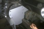
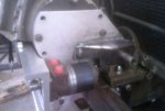
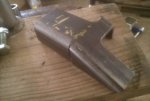
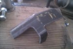
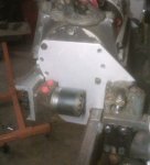
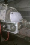
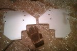
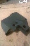
In the pics you can see the silver side plates for the winch, then the front aluminum machined piece for the oil motor offset and chain drive, then the outer part to form the completion of the clevis style mount for the upper mount. Silver plate is 3/8" steel plate, aluminum offset is 5/8" where it matters, and outer clevis part (that was rect tube but modified a LOT) is 1/4" thick.
I left room between the motor and implement mount in case that motor just isn't quite enough...the next model has nearly twice the inch-pound rating and will bolt right in.
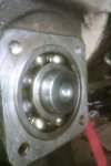
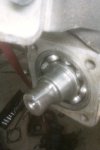
The worm or pinion of the winch was pulled and flipped so that the original yoke side is now at the front. I polished up where the seal will ride and cut a 1/4" keyway in it to fit the TSC sprocket hubs I bought and modified to fit this project. The rear of the pinion was cut off for clearance of a factory front Unimog PTO front output. Enough room was left on the shaft so that the seal will work in the rear bearing retaing/seal plate.
I have a cover made up for the front chain drive but not pictured. Next couple things to do are to unbolt the bumper, drill the two holes for the lower mounts, reinstall, then bush the 7/8" lower mounting pins and weld them onto the winch side plates.
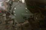
Oh, I wanted to gain some extra side to side room so I removed the driver's side cover of the winch, clamped it down in my mill and plowed .600" off of the two heavy mounting stand-offs cast into that cover. So far its coming along pretty well...but taking a little bit picking at it a couple hours at a time.
Attachments
-
41.3 KB Views: 111
-
42.8 KB Views: 84
-
33.9 KB Views: 94
-
35.2 KB Views: 102
-
38.7 KB Views: 96
-
37.2 KB Views: 101
-
32.7 KB Views: 107
-
37.8 KB Views: 135
-
38.5 KB Views: 119
-
51.1 KB Views: 100
Last edited:


