• Steel Soldiers now has a few new forums, read more about it at: New Munitions Forums!

  • Microsoft MSN, Live, Hotmail, Outlook email users may not be receiving emails. We are working to resolve this issue. Please add support@steelsoldiers.com to your trusted contacts.

Pre Purchase MEP 710a questions

alphamale

New member
9
0
0
Location
mocksville, nc
Pre Purchase MEP 701a questions

(Corrected model in title)

Hello

I have been reading and shopping for a few weeks. There is a generator owned by a guy that is actively answering my questions and out of this has arisen two worry points I am looking for input on:

1. Small occasional oil drip from within the oil drain tube.
2. Wet spot near where the gen meets engine

I am not a mechanic but I can ...sometimes...handle small things with my small engines.

The generator would be used for emergency back up of a few items like refrigerator and a cpap and an oxygen concentrator and a light. I don't want to buy trouble, that's why I have not got one from a store.

I think it operates perfectly otherwise. Rebuild material must be hard to find. I looked and found lots of websites that offer you a quote but I bet they have no inventory if you do ask.

Any advice or insight would be appreciated. Thank you.
 
Last edited:

Isaac-1

Well-known member
1,970
50
48
Location
SW, Louisiana
I assume you mean MEP-701a, in which case I would look for the source of the leak, it may be a hose that is about to fail due rubbing on part of the frame, if no obvious cause is found, monitor it and don't worry too much. Also on this model check the voltage output both AC and DC to make sure the voltage regulators are working right, it seems that the DC charging regulator on these is prone to go high after it warms up and cooks the battery.
 

alphamale

New member
9
0
0
Location
mocksville, nc
Thanks, also for the model correction, I fixed it.

I will allow it to warm up and check that.

The oil from the inside of the drain hose would seem to be the valve not closing?????
 
Last edited:

alphamale

New member
9
0
0
Location
mocksville, nc
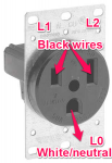
Question so i can understand what has been written in using the 240 split phase capability when a white wire is runs from panel frame to backside lug LO.

Welding receptacle NEMA 6-50R, + 6 gauge 3 wire
Lug LO is the neutral and is it attached to the bottom V blade configuration of the receptacle?

Then Run one black wire to L1 and the other black wire side to L2? It does not matter which side is left side or right side of the receptacle? Is any of this correct? And again the bottom slot on the v is for the white wire which is now neutral
Thank you

plug markup.png

With a #6 3 wire outdoor/indoor epdm cable (oil/water) this may have 2 black and one white wire

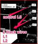
load terminals markup.JPG


Do I have the wires going to the correct place?
 
Last edited:

Isaac-1

Well-known member
1,970
50
48
Location
SW, Louisiana
Ok, this is a whole can of worms, officially the MEP-701a DOES NOT output 120/240 split single phase, it outputs either 120V only single phase, 240V only single phase with no neutral, 120/208 3 phase, or a special 120V only 3 phase mode. In reality it seems the vast majority of the units in the field were either factory wired or were modified to output 120/240 split single phase (common household current), however the lugs used for the output depend on the operating mode you choose, and so does the use of the grounding strap, usually on the back side of the output lugs inside the control box. See this old thread on the topic http://www.steelsoldiers.com/showth...01A-MEP-016b-Voltage-Selector-Ground-Question it is one of many threads that address this issue.

Ike

p.s. the NEMA 6-50R is the wrong outlet to be using in this case for several reasons, first it is NOT 120/240V outlet is is a 240V only outlet, and the point you have marked as L0 is in fact the ground prong. Also the MEP-701a when wired for 120/240V mode can only generate around 15 amps at 240V (officially a bit less)

You might also want to look at this old thread, in general I feel the MEP-016 family of generators should not be connected 120/240V unless their is a specific reason as they are simply too small to run most 240V loads (maybe some well pumps) and you increase your risk of burning out the windings by overloading them with an unbalanced 120V load. http://www.steelsoldiers.com/showthread.php?86145-What-size-generator-needed
 
Last edited:

alphamale

New member
9
0
0
Location
mocksville, nc
I read those threads and used that to try and understand and ask my questions. I tried to make clear I did not know what I was doing and that was the reason I was asking and using photos so someone could tell me what I was doing wrong and tell me how to do it right.

That was the receptacle I wanted to use. But your point is taken. I was trying to figure out what wire goes where. I thought the neutral was ground.

I am glad you know the difference.
 

alphamale

New member
9
0
0
Location
mocksville, nc
I just want to know how to use this machine. I have read everything. The selector switch is not hard to figure out. The lugs you connect the machine with have been clearly identified in one or more posts in their role.

So I need to understand how to translate the 3 wires used by my stuff to the 4 lugs that emit the power the machine makes. Lastime I looked an electrical cord had white, black, green wire.

So to start I could not figure out what lug the green wire goes on. I also think the other two wire colors vary but consist of white and black and can be interchanged. So which of the lugs match up to the 3 wires.

My machine has a ground strap on the frame along with a white wire that disappears behind the lug panel. I understand those play a role along with the selector switch.

I am first trying to figure out the most basic 3 wire question and if I may, will come back to the trough once I get that far.

I have lights, I have refrigerators all those things interest me in running on the generator. But what frustrates me is the basic question I have presented.

Thank you for asking
 
Last edited:

DieselAddict

Well-known member
Steel Soldiers Supporter
2,488
1,900
113
Location
Efland, NC
The best thing to do is run it in 120v mode and power your selected items from extension cords. As stated earlier the generator doesn't make dual voltage 120/240v without modification so connecting it to your power panel is not practical.
 

alphamale

New member
9
0
0
Location
mocksville, nc
Thanks, but you did not answer the question. You are incorrect in your assumption. This kinda of response is not very helpful to me. I guess I need to ask an electrician and I will come back and update my post and answer my own question and maybe sometime someone else can benefit.

Man is that annoying.
 

DieselAddict

Well-known member
Steel Soldiers Supporter
2,488
1,900
113
Location
Efland, NC
What is confusing me is you indicate running 120v household appliances in your first post but you show a 240v plug. That generator will not work for that setup.

Can an you answer how you intend to connect the appliances to the generator?
 

212sparky

Well-known member
1,822
38
48
Location
Monroe/ Ohio
From your generator you will need to run a 6 AWG 4 conductor cable. It should have a Black, Red, White and Green. Black and Red go to your "hot" lugs, never inter mix a white other wise you could kill someone or burn your generator down. On your generator you will want to disconnect the bond of the neutral "L0" and ground since this will be. Bonded in your main panel. Connect White to L0 and Green to the generator frame ground point.

You will need a transfer switch our interlock in your panel to keep from back feeding the grid in an outage and severely injuring someone. Once that is taken care of you will need a female 50 amp 120 /240 volt female cord end and an inlet box that has the male pins in the box. You need this so if the generator was started and not connected their would not be and exposed live parts.

To answer your 2 original questions the oil drip sounds like the valve is weeping. The second I would just keep am eye in it and make sure all mount bolts are tight.
 

tim292stro

Well-known member
2,118
40
48
Location
S.F. Bay Area/California
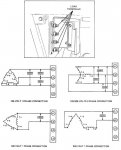
You will find in life that it's kinda hard to get answers if you bite off people's heads when they offer answers. Even if you're annoyed, just letting it go is the best option. As it happens, I dug through the TM for the MEP-016a/701a and I can't find any indication that you can do a 240/120 split with this generator set...

MEP-016_MEP-701a_wiring.jpg

The problem is the winding count - there just aren't enough windings to do a 240/120 split at the head. Yes, you can do 120V and you can do 240V single phase, but you can't do split 240/120 without doubling the windings. The only way you're going to get a neutral out of that head is if you do a 3-phase (208Y/120V)


Also, forcing people to help you re-task existing plugs to something that won't pass a code inspection is probably not going to happen out in the open on this forum - it's a legal liability for anyone to suggest that you do something "unexpected" when looking at a standard plug. That's how people get killed with electricity and is specifically why there is a formalized an adopted electrical code. I'm going to go out on a limb and say that if you ask a LICENSED electrician to help you figure out how to wire up the wrong outlet to a generator that can't do what you want, you're not going to get a lot of help...

You should not hook up a 240V generator to a system that is expecting a 240/120 single-phase with a neutral center tap. If you do this and turn on a 120V load, you will have an imbalanced voltage on the generator - the load drawing the lowest current will see the highest voltage (this means the high-current load will see less than 120V, while the low-current load will see much more than 120V). You are likely to start an electrical fire this way.

About the only way I can think you're going to be able to hook this into a 240/120 house is to use a 1:1 transformer with a center-tapped secondary winding.
 
Last edited:

1800 Diesel

Member
768
26
18
Location
Santa Rosa County, FL
Thanks, but you did not answer the question. You are incorrect in your assumption. This kinda of response is not very helpful to me. I guess I need to ask an electrician and I will come back and update my post and answer my own question and maybe sometime someone else can benefit.

Man is that annoying.
Sir, you clearly lack a fundamental understanding of household wiring circuits & the means to safely & legally connect a generator to your system. I understand you are frustrated as we all have been but your tone will not encourage folks to offer assistance. I would suggest you take a step back and show some patience & respect to people willing to give of their time attempting to help & just maybe save you from making some serious & life or property-threatening mistakes....lining up an electrician would be a great idea but both of you still need to know the output connections and proper configuration of your generator.
 

Isaac-1

Well-known member
1,970
50
48
Location
SW, Louisiana
Wow this thread has certainly taken a nose dive in the last few hours,

alphamale: As others have said it seems you lack a basic understanding of household wiring, and I don't mean for this post to complete fix that, but perhaps it will get you on the right path. Household power in the U.S. is typically what is called 120/240V split single phase, often called 120/240, 120/240 single phase, or just single phase for short. A typical household panel has 4 important wires, L0, L1, L2 and ground. The ground wire which is typically bare or green is there as sort of a safety net, and should only carry current in the event of a wiring fault. This leaves L0 (neutral), L1 (hot) and L2 (hot), the voltage between either L1 - L0 or L2 -L0 will be 120V and the voltage between L1-L2 will be 240V. Typical small appliances are powered by 120VAC, this includes home lighting, refrigerator, tv, etc. Electric dryers, central air conditioners, electric water heaters, electric stoves, and other things with high wattage draws will typically be 240VAC. The breakers in your breaker panel connect the outlets on these various appliances to their proper line connections, this might be 120VAC with a line to neutral, or may be 240V with two hot lines connected along with a ground wire, or it may even be 4 wires with both hots, the neutral and a ground wire connected to supply 120/240V at the same time as is typically found on newer electric dryers with 4 prong plugs. The outlet in your illustration above is a 240V only outlet with a safety ground.

You mention cords with 3 wires, (white,black, and green) this is the color code for a typical 120VAC appliance where white is connected to L0 (neutral), black is connected to either L1 or L2 (your hots), and green is connected to the ground wire.

Above I asked how you plan to use your generator, I asked this to help narrow down the topic. For example the way you would want to set up a generator that is being mounted on a trailer for portable use is very different from how you would set it up as a fixed home standby, or how you might set it up at an off grid cabin. There are key electrical code differences in each of these, as well as the issue of connecting it to your home wiring vs mounting outlets at the generator and using extension cords or a power distribution box.

We can try to start over on the wiring issue, but it really can't be answered using the illustrations in your message, it is a square peg round hole sort of problem.

DieselAddict: the chart on page 107 you reference has mistakes in it, in fact that manual is full of them, for one thing the line to line voltage for the 240V connection is incorrectly shown as 120V, also it seems most units in the field were modified to have 120/240 split single phase, not the 240V only as shown in the manual, this is covered in the links I posted earlier.

212Sparky: Where do you get ANY of that, this generator can only supply about 30 amps at 120V only, or 15 amps at 120/240VAC there is NO need for 6AWG wire at any of those levels and a 50 amp cord is massive overkill

tim292stro: see above about mistakes in the TM

Ike
 

212sparky

Well-known member
1,822
38
48
Location
Monroe/ Ohio
Wow this thread has certainly taken a nose dive in the last few hours,

alphamale: As others have said it seems you lack a basic understanding of household wiring, and I don't mean for this post to complete fix that, but perhaps it will get you on the right path. Household power in the U.S. is typically what is called 120/240V split single phase, often called 120/240, 120/240 single phase, or just single phase for short. A typical household panel has 4 important wires, L0, L1, L2 and ground. The ground wire which is typically bare or green is there as sort of a safety net, and should only carry current in the event of a wiring fault. This leaves L0 (neutral), L1 (hot) and L2 (hot), the voltage between either L1 - L0 or L2 -L0 will be 120V and the voltage between L1-L2 will be 240V. Typical small appliances are powered by 120VAC, this includes home lighting, refrigerator, tv, etc. Electric dryers, central air conditioners, electric water heaters, electric stoves, and other things with high wattage draws will typically be 240VAC. The breakers in your breaker panel connect the outlets on these various appliances to their proper line connections, this might be 120VAC with a line to neutral, or may be 240V with two hot lines connected along with a ground wire, or it may even be 4 wires with both hots, the neutral and a ground wire connected to supply 120/240V at the same time as is typically found on newer electric dryers with 4 prong plugs. The outlet in your illustration above is a 240V only outlet with a safety ground.

You mention cords with 3 wires, (white,black, and green) this is the color code for a typical 120VAC appliance where white is connected to L0 (neutral), black is connected to either L1 or L2 (your hots), and green is connected to the ground wire.

Above I asked how you plan to use your generator, I asked this to help narrow down the topic. For example the way you would want to set up a generator that is being mounted on a trailer for portable use is very different from how you would set it up as a fixed home standby, or how you might set it up at an off grid cabin. There are key electrical code differences in each of these, as well as the issue of connecting it to your home wiring vs mounting outlets at the generator and using extension cords or a power distribution box.

We can try to start over on the wiring issue, but it really can't be answered using the illustrations in your message, it is a square peg round hole sort of problem.

DieselAddict: the chart on page 107 you reference has mistakes in it, in fact that manual is full of them, for one thing the line to line voltage for the 240V connection is incorrectly shown as 120V, also it seems most units in the field were modified to have 120/240 split single phase, not the 240V only as shown in the manual, this is covered in the links I posted earlier.

212Sparky: Where do you get ANY of that, this generator can only supply about 30 amps at 120V only, or 15 amps at 120/240VAC there is NO need for 6AWG wire at any of those levels and a 50 amp cord is massive overkill

tim292stro: see above about mistakes in the TM

Ike
I was going off the numbers he had supplied earlier in the thread. Figured it was an exhisting run or something similar.
 

alphamale

New member
9
0
0
Location
mocksville, nc
I am sorry I annoyed everyone else. Thanks for the information. I dug and found what I think was missing. I found it in an old article entitled "primary power for c-e systems" by Kenneth tollstam Jr.

"Some technical manuals for the power generator equipment do not give any guidance for connecting the equipment grounding conductor, EGC.". I will stop with the quote there because that was the flaw I saw. I read what you guys write and that is the missing piece of information. By the way like in this thread one guy says you can't and in fact you can. I find that annoying. I do not speak military generator, by cracke I will learn. The mentioned article does in fact give examples on grounding. Simple, with pretty pictures.

I was going to design a board with a junction box not attached to my home wiring whereby I used a extra welding plug to connect the generator to the board (wood) supplying juice to 3 areas, a receptacle behind my refrigerator, next to my normal outlet and a duplex in my bedroom. If lose power I plug the generator using the spare welding plug into a junction box and it powers my fridge, my cpap and my oxygen concentrator and a light on a string. I know that generator will power those things.

I read twice being warned about back feeding my panel. That's annoying and a waste of time. You know the answer, say it, or don't, just don't try and read my mind.

That article has a part one that's on grounding the generator which is appropriate. The army has some messed up routing problem and the archived article (spring 1980) will not display. I would love to read it.

So as a totally annoying noob you guys would be very helpful to enlighten the world on grounding from top to bottom.
 
Last edited:

alphamale

New member
9
0
0
Location
mocksville, nc
My electrician just put in a welding plug that has 2 50amp breakers for me. He said I could use that with an interlock and not have to put 2 outlets in. To me two outlets is the simple fix for a 3kw generator. I can use the outlets to exercise the generator also while my home was power.

He also thinks I should have bought a big engine driven welder and used it instead. I guess besides annoying I am independent.
 

Isaac-1

Well-known member
1,970
50
48
Location
SW, Louisiana
Part of the problem with grounding is it is NOT a simple issue, and depends on a lot of details for how you do it and still be code compliant even if the basic concept is fairly straight forward, in addition the NEC code as it relates to generator installation has been extensively revised in the last 10-15 years at least 3 times, so what was code legal 10 or 20 years ago may not be today. As a result even many electricians that install generators from time to time get things wrong when it comes to this part of the electrical code.

Having said that if you are going to run a completely separate system that does not connect to your home power system and you will just move the plug over to the generator powered only outlet in the event of an outage things should be fairly simple, as this is basically the way the army intended these units to operate in "island mode".

If all of your outlets that you plan to power are 120VAC, here is how I would do it:

(someone correct me if there is a code violation I missed, as I don't do this for a living)

I would drive a ground rod at the generator, and have the neutral ground jumper installed and connect the generator to the ground rod and set the generator for 120V single phase only

then use a length of cord on the generator with an twist lock L5-30 receptacle (cheapest way to get is probably an L5-30 extension cord (120V only 3 wire 30 amp twistlock) and cut off the plug end and wire this to the output lugs, L5-30 cords are commonly used for marine / boat application in marinas, and finding cheap used ones with damaged plug ends is fairly easy, you just need one with a bad plug and good receptacle, 25 or 30 ft are the most common lengths)

Get an L5-30 inlet box and mount this on the side of the house, from this I would feed a small 6 or 8 circuit main breaker pane with an appropriate number of 15 or 20 amp breakers running to each dedicated generator only outlet.

Total investment cost probably under $200 + wiring cost. $50-75 for a used 30 amp marine cord, $30-$40 for the inlet box, another $50-$75 for the small (60 -70 amp) breaker box and breakers, add in 4 or 5 15-20 amp outlets at $5-$15 each depending on if they are GFCI or not, most places require GFCI for all outlets in living spaces as of the latest NEC code, excluding refrigerators due to chance of false tripping when connected to compressors.
 
Top