windrac
New member
- 11
- 25
- 3
- Location
- Indianapolis, IN
All,
As an owner of two gasser M35s, I went looking for details on the oil system when it came time to referb that subsystem. Despite my searching, I found information kind of hard to find, so this post is my attempt to collate this information in one place for future readers who might be looking for the same information.
Basic specs:
- Oil Capacity: 9qt
- Oil Filter: NAPA 1500 cartridge-style
- Oil Type: 10W-30
- Oil Circuit: Dual Circuit Filter Bypass (See bottom of this post for more detail on this)
While I was searching, I found this thread elsewhere on this forum here that talked about conversion to single-circuit oil filtration, but it didn't have the level of detail I wanted. The below post is just replicating that thread but with more pictures / details. I give credit for the idea to the users over on that thread. Thanks for the good info!
With that being said... let's begin.
Background on my truck in the pictures below: It was owned by a family member and ex-SEABEE. It hadn't run in 30 years, and I am restoring it in his memory.
I started by draining the oil and removing the old filter assembly and related components. I found that the filter installed was actually from NAPA, part number 1500.
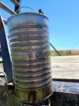
I removed the filter housing and associated bracketry. Use a 1/2" wrench to get the fittings off the hoses to the block. Keep that bracket for the filter housing, we'll use that later...
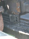
Next I pulled the oil hose cap off the side of the block, and this is what I found underneath...
I don't know what the that plate directly above the oil plate is, but the bottom center bolt holds the heat shield on, and when you remove it, it starts seeping coolant. Just... minimize the amount of time that bolt is out.
Here is the plate that came off of the engine:
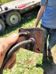
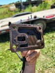
Without going into extreme detail about how the old oil circuit ran (I can draw a diagram of this if someone requests it below), these three holes serve the following purposes:
Top Hole: Filtered oil to the top of the engine
Middle Hole: Return to crankcase
Bottom Hole: High pressure oil from pump
Thus, we will be blocking off the middle hole and using the bottom hole as the filter input, and the top hole as the filter output.
So step 1 was to cut a piece of 1/2" flat steel for our new plate. This is the OEM thickness of the plate we just removed in the photos above. Then transfer punches were used to transfer the location of the four mounting holes:
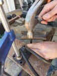
I added a "TOP" marking just to keep the orientation correct...
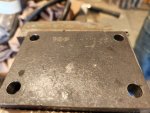
Next we need to locate those two holes (input and output) mentioned above. This can be kind of tricky, so the following method was used.
Only one hole in the OEM plate lines up with the three holes in the block - the crankcase return hole. So that was used to locate the other two holes. Notice in the picture above, there are two indentations made by transfer punches - the lower one is the crank return hole after the hose was removed, and the top one was made by using a square to score a vertical line, and a set of dial calipers to get the distance of the top hole from the middle hole. This should give us the location of the FROM FILTER hole.
Next we need to locate the TO FILTER hole. This was done by measuring the distance to that hole on the block from the first two holes. As I'm sure you all remember from geometry, two circles that overlap have two intersect points. Thus, one of these intersect points was used to locate the third hole. Notice in the picture above at the bottom left, the two arc-shaped score lines. These are from the two transfer punch marks, at radial distances measured on the block. The intersection of these two arc lines is the center of the third hole!
After center drilling the two desired holes, and adding some text markings...
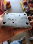
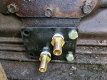
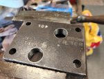
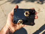
Now we need to add NPT fittings. We are going to be using 1/2" ID heater hose tubing, so get some 1/2" barb fittings. I used a 1/2" NPT tap. I DO NOT RECOMMEND THIS. It's just the tap I had, and I had some other projects that needed this size, so that's what I used. I would recommend 3/8 NPT for future people doing this project. That bottom hole is awfully close to the edge of the block to hold 60psi of hot oil.
To recap:
- What I used: 1/2 barb to 1/2 NPT
- What YOU Should use: 1/2 barb to 3/8 NPT
After tapping:
And after some painting and installing the barbs:
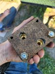
And I took a sheet of cork gasketing and cut out a gasket, using two of the mounting holes to hold it in place while I cut the holes out with a box cutter.
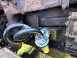
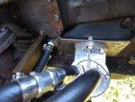
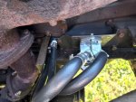
Now to mount it all back up. One thing I did NOT get a picture of was modifying the heat shield. I had to cut the bottom bolt hole off because it was hitting the 1/2NPT fitting on the new block. If you used 3/8NPT fittings, this probably wouldn't have happened
As an owner of two gasser M35s, I went looking for details on the oil system when it came time to referb that subsystem. Despite my searching, I found information kind of hard to find, so this post is my attempt to collate this information in one place for future readers who might be looking for the same information.
Basic specs:
- Oil Capacity: 9qt
- Oil Filter: NAPA 1500 cartridge-style
- Oil Type: 10W-30
- Oil Circuit: Dual Circuit Filter Bypass (See bottom of this post for more detail on this)
While I was searching, I found this thread elsewhere on this forum here that talked about conversion to single-circuit oil filtration, but it didn't have the level of detail I wanted. The below post is just replicating that thread but with more pictures / details. I give credit for the idea to the users over on that thread. Thanks for the good info!
With that being said... let's begin.
Background on my truck in the pictures below: It was owned by a family member and ex-SEABEE. It hadn't run in 30 years, and I am restoring it in his memory.
I started by draining the oil and removing the old filter assembly and related components. I found that the filter installed was actually from NAPA, part number 1500.

I removed the filter housing and associated bracketry. Use a 1/2" wrench to get the fittings off the hoses to the block. Keep that bracket for the filter housing, we'll use that later...
Next I pulled the oil hose cap off the side of the block, and this is what I found underneath...
I don't know what the


Here is the plate that came off of the engine:


Without going into extreme detail about how the old oil circuit ran (I can draw a diagram of this if someone requests it below), these three holes serve the following purposes:
Top Hole: Filtered oil to the top of the engine
Middle Hole: Return to crankcase
Bottom Hole: High pressure oil from pump
Thus, we will be blocking off the middle hole and using the bottom hole as the filter input, and the top hole as the filter output.
So step 1 was to cut a piece of 1/2" flat steel for our new plate. This is the OEM thickness of the plate we just removed in the photos above. Then transfer punches were used to transfer the location of the four mounting holes:

I added a "TOP" marking just to keep the orientation correct...

Next we need to locate those two holes (input and output) mentioned above. This can be kind of tricky, so the following method was used.
Only one hole in the OEM plate lines up with the three holes in the block - the crankcase return hole. So that was used to locate the other two holes. Notice in the picture above, there are two indentations made by transfer punches - the lower one is the crank return hole after the hose was removed, and the top one was made by using a square to score a vertical line, and a set of dial calipers to get the distance of the top hole from the middle hole. This should give us the location of the FROM FILTER hole.
Next we need to locate the TO FILTER hole. This was done by measuring the distance to that hole on the block from the first two holes. As I'm sure you all remember from geometry, two circles that overlap have two intersect points. Thus, one of these intersect points was used to locate the third hole. Notice in the picture above at the bottom left, the two arc-shaped score lines. These are from the two transfer punch marks, at radial distances measured on the block. The intersection of these two arc lines is the center of the third hole!
After center drilling the two desired holes, and adding some text markings...

Now we need to add NPT fittings. We are going to be using 1/2" ID heater hose tubing, so get some 1/2" barb fittings. I used a 1/2" NPT tap. I DO NOT RECOMMEND THIS. It's just the tap I had, and I had some other projects that needed this size, so that's what I used. I would recommend 3/8 NPT for future people doing this project. That bottom hole is awfully close to the edge of the block to hold 60psi of hot oil.
To recap:
- What I used: 1/2 barb to 1/2 NPT
- What YOU Should use: 1/2 barb to 3/8 NPT
After tapping:

And after some painting and installing the barbs:

And I took a sheet of cork gasketing and cut out a gasket, using two of the mounting holes to hold it in place while I cut the holes out with a box cutter.

Now to mount it all back up. One thing I did NOT get a picture of was modifying the heat shield. I had to cut the bottom bolt hole off because it was hitting the 1/2NPT fitting on the new block. If you used 3/8NPT fittings, this probably wouldn't have happened
Last edited:


