I don’t think the ground wire makes any difference in operation, I believe it was done to meet some EMI/shielding specification, since they didn’t tie the CTIS case to ground in the cannon plug. Just like they put EMI filters on the wiper, washer and heater blower motor circuits...
In the A1 and A1R drawings I have seen, the CTIS doesn’t appear to use the data busses in operation. It still gets it’s speed input separately(from speedometer) and sends out it’s overspeed signal via hardwire to the MMDC And gets a blackout(dimmer) signal from the lighting circuits. That and it’s own display lights are it’s only interfaces with other truck systems and the operator, same as in an A0... I think they tied it in to the busses simply to make it more easily accessible for a technician to connect to and communicate with all the controllers on the truck From a single port.
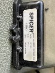
Is that CTIS module doing what its supposed to do/fully functional?
If so, you can research wether yours is the right unit or not and if not replace it.
Or
You can open up the cannon plug on the harness and disconnect the 4 wires used by the two comms busses, insulate/heat shrink the ends of the wires and move on to something else to occupy your time(and wallet)
")