

jacobsk
Member
- 66
- 0
- 6
- Location
- Appleton, Wisconsin
Hey all! Me again, I wanted to share a quick value-add project that the wife unit and I completed this afternoon to make MEP-002a ownership a bit easier and if you’re like me will hopefully keep the wife unit off your back when it comes to having a thousand pound generator taking up space in your garage.
If you haven’t seen my other thread about how not to unload a MEP-002a, well rest assured this idea was thought out much more thoroughly and for me personally should prevent any legs from getting caught underneath a MEP.
If you’re one of those lucky folk who have the ability to scoop up your MEP and move it around with a piece of heavy equipment, I’m jealous. If you’re like me and you live in the middle of a city, you might find it impractical to use the tractor or fork lift that you don’t have to move your MEP around in your tiny garage which by the way you couldn’t even park a car in if it wasn’t filled with surplus military equipment.
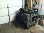
In order to buy this MEP, my second one now, the wife unit made me sell a welding table (I’d been clinging dearly to since we got married) in order to make room to store the generator in the back corner of the garage. No big deal, I pulled the table from a dumpster when I was in college and I’ve never even owned a welder, but the table sits in a peculiar spot tucked away in the back corner of the garage where I have absolutely no way to move the MEP into. I got $100 for the table on craigslist and was faced with another dilemma, how the heck do I move this beautiful Onan masterpiece around, let alone anywhere?
I needed a rolling platform for the MEP-002a so that I could muscle it around and into tight spaces. Pull it out for hookup , use, maintenance, cleaning, admiring, whatever, it had to be mobile and I don’t have any other way to move the darn thing.
Being the frugal guy that I am, and to keep the wife unit off my back, I had to keep it under the cost of a set of Norwex brand wash rags which the wife unit chose to flush $50 on yesterday, $50 bucks it is I said to myself as I looked through my online bank statement and headed out the door to the hardware store.
$8.09 QTY 2 – 8ft 2x6 lumber
$3.70 QTY 16 – 4 inch carriage bolts, washers, lock washers, and nuts
$25.16 QTY 4 – 5 inch 330 pound rated swivel casters
$Free QTY 16 – 2 ½” wood screws (free because who doesn’t have these lying around?)
Paint – optional, used about ½” off the top of a can of color matched BEHR exterior flat that I bought previously to touch up the marks left from dumping the MEP on its side last Wednesday. That green did add the final touch though so maybe it should be mandatory that it’s painted.
The total came to $36.95 after tax. I didn’t include paint because I already had it and you don’t need it to complete the job. I think I’ll get more use out of this generator than some crummy Norwex rags which are bound to end up as wash rags for the truck before long, the wife unit didn’t balk at the $37 so I think I’m in the clear.
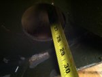
To start I measured the inside of the MEP frame where I wanted the platform to nest. The inside of the frame length-wise is just over 47 inches so I rounded it down to 47” even and figured the weight of the generator would seat if there was any minimal interference lengthwise. Next I measured the width of the inside of the skids, just under 27 ½ inches, so I rounded it down to 27 ¼ inches so that if I had to fight any subtle interference it would be only in one direction.
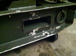
The intent is to make a frame which sits inside the generators skids, and nestles between the frame under the engine blower shroud and the engine-side fork pocket. This end is the most critical because the measurement from the inside of the engine-side skid frame and the engine-side fork pocket is a mere 5 ¼ inches. Because the bottom of the fork pockets are welded higher in the frame then the ends of the skid frame this rolling platform can rest below fork pockets and support the weight of the unit, while nesting comfortably inside all four sides of the skid frame so that the unit cannot slide off in any direction... and land on your leg.
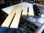
I cut the two 2x6’s into four pieces, two 47” long boards and two 27 ¼” long boards. Next I ripped the two 27 ¼” pieces down from their stock dimension of 5 ½ inches to 5 ¼ inches wide so that this piece could nest underneath the engine without any interference. If you don’t have a table saw to rip these boards you could do it with a circular saw carefully, and realistically the dimension just needs to be less than 5 ¼” so a 2x4 would work as well. In addition if you really wanted to save time you would only need to rip one end since there is no potential interference on the control box side of the generator as the fork pockets are biased to the engine side of the frame. Lastly I then sanded the splinters off all of the fresh cuts because who likes slivers?
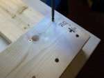
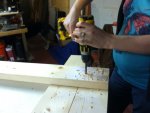
Next I laid the four pieces out on the table and predrilled each corner for four 2 ½” wood screws to hold the frame together. I measured in 1” from each corner and drilled 3/32 pilot holes then ran in the screws making sure the frame was square by measuring the diagonal dimension and ensuring both diagonals were the same. I kept the screws on the perimeter of each corner because the castors get mounted in this location.
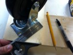
I then asked the wife unit to help lay out the casters, we argued about the benefits of squaring the mounting flanges with the frame or placing them at a diagonal. “I’ll never be able to describe how to lay out a diagonal to the guys on SteelSoldiers” I said, to which she replied “if you place them at an angle you’ll be less likely to apply a heavy moment perpendicular to the short side of the mounting flange, making the joint stronger. Plus you’ll offset the holes being drilled through the grain of the lumber, lowering the likelihood of splitting the boards due to the alignment of the holes and the grain.” I guess it helps to have a wife who is a design engineer, though sometimes it makes online write-ups a bit more difficult. I decided to mount casters out at an angle because 1.) happy wife = happy life!, and 2.) she was right.
The wife unit (preggers too!) used a 3/8 inch drill bit to drill a clearance hole for each of the four caster bolts on all four corners. The carriage bolts are 5/16" diameter and the square under the head mates with the slot in each of the caster mounting flanges. I chose 4” carriage bolts because I knew I had to go through 3 inches of 2x6 material and I didn’t want to end up being a few threads too short once I had the washers installed. In hindsight I probably could have gotten away with 3 ½ inch carriage bolts just fine.
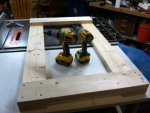
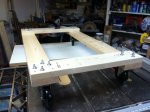
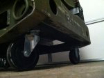
We assembled the casters to the frame and flipped it over - taaada! I now have a rolling cart for the MEP-002a. The overall dimensions are 47 inches long by 27 ¼ inches wide. The two short ends are mounted on top of the long sides (on the opposite side of the frame as the casters) so that the part underneath the engine nests between the fork pocket and the end of the skid frame. If you’re confused go look at your generator’s frame and you’ll understand what I am talking about. I have no doubt that if you’re one of the folks with a MEP-003a that you could simply lengthen the dimensions of the 47 inch frame so that it fit your machine. It might be wise to check the capacity of any casters you buy so that they’ll hold up to the extra weight of the 10kw unit.
I tried to replicate true CARC paint by slobbering 3x as much paint as necessary onto the frame and completely covered the caster hardware so that any attempt to remove or replace it will be a true exercise in frustration – just like the real thing. The green adds a touch of class and matched my MEP’s stock color almost perfectly.
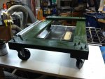
Lastly I used my hi-lift jack and some chain to lift the MEP one end at a time onto some jack stands in order to roll the cart underneath and in place. I slowly lowered the generator ensuring that the rolling cart nested where intended. The frame allows for clearance from the caster wheels to the skids, raises the height of the generator about 5 inches, keeps the fork pockets free and available for when I do eventually "accidentally" win a skid steer on GL, and can be moved by myself individually with a fair amount of effort. No it’s not easy, but neither is convincing my wife that I need a tractor, trust me I’ve tried.
Enjoy!
If you haven’t seen my other thread about how not to unload a MEP-002a, well rest assured this idea was thought out much more thoroughly and for me personally should prevent any legs from getting caught underneath a MEP.
If you’re one of those lucky folk who have the ability to scoop up your MEP and move it around with a piece of heavy equipment, I’m jealous. If you’re like me and you live in the middle of a city, you might find it impractical to use the tractor or fork lift that you don’t have to move your MEP around in your tiny garage which by the way you couldn’t even park a car in if it wasn’t filled with surplus military equipment.
In order to buy this MEP, my second one now, the wife unit made me sell a welding table (I’d been clinging dearly to since we got married) in order to make room to store the generator in the back corner of the garage. No big deal, I pulled the table from a dumpster when I was in college and I’ve never even owned a welder, but the table sits in a peculiar spot tucked away in the back corner of the garage where I have absolutely no way to move the MEP into. I got $100 for the table on craigslist and was faced with another dilemma, how the heck do I move this beautiful Onan masterpiece around, let alone anywhere?
I needed a rolling platform for the MEP-002a so that I could muscle it around and into tight spaces. Pull it out for hookup , use, maintenance, cleaning, admiring, whatever, it had to be mobile and I don’t have any other way to move the darn thing.
Being the frugal guy that I am, and to keep the wife unit off my back, I had to keep it under the cost of a set of Norwex brand wash rags which the wife unit chose to flush $50 on yesterday, $50 bucks it is I said to myself as I looked through my online bank statement and headed out the door to the hardware store.
$8.09 QTY 2 – 8ft 2x6 lumber
$3.70 QTY 16 – 4 inch carriage bolts, washers, lock washers, and nuts
$25.16 QTY 4 – 5 inch 330 pound rated swivel casters
$Free QTY 16 – 2 ½” wood screws (free because who doesn’t have these lying around?)
Paint – optional, used about ½” off the top of a can of color matched BEHR exterior flat that I bought previously to touch up the marks left from dumping the MEP on its side last Wednesday. That green did add the final touch though so maybe it should be mandatory that it’s painted.
The total came to $36.95 after tax. I didn’t include paint because I already had it and you don’t need it to complete the job. I think I’ll get more use out of this generator than some crummy Norwex rags which are bound to end up as wash rags for the truck before long, the wife unit didn’t balk at the $37 so I think I’m in the clear.
To start I measured the inside of the MEP frame where I wanted the platform to nest. The inside of the frame length-wise is just over 47 inches so I rounded it down to 47” even and figured the weight of the generator would seat if there was any minimal interference lengthwise. Next I measured the width of the inside of the skids, just under 27 ½ inches, so I rounded it down to 27 ¼ inches so that if I had to fight any subtle interference it would be only in one direction.
The intent is to make a frame which sits inside the generators skids, and nestles between the frame under the engine blower shroud and the engine-side fork pocket. This end is the most critical because the measurement from the inside of the engine-side skid frame and the engine-side fork pocket is a mere 5 ¼ inches. Because the bottom of the fork pockets are welded higher in the frame then the ends of the skid frame this rolling platform can rest below fork pockets and support the weight of the unit, while nesting comfortably inside all four sides of the skid frame so that the unit cannot slide off in any direction... and land on your leg.
I cut the two 2x6’s into four pieces, two 47” long boards and two 27 ¼” long boards. Next I ripped the two 27 ¼” pieces down from their stock dimension of 5 ½ inches to 5 ¼ inches wide so that this piece could nest underneath the engine without any interference. If you don’t have a table saw to rip these boards you could do it with a circular saw carefully, and realistically the dimension just needs to be less than 5 ¼” so a 2x4 would work as well. In addition if you really wanted to save time you would only need to rip one end since there is no potential interference on the control box side of the generator as the fork pockets are biased to the engine side of the frame. Lastly I then sanded the splinters off all of the fresh cuts because who likes slivers?
Next I laid the four pieces out on the table and predrilled each corner for four 2 ½” wood screws to hold the frame together. I measured in 1” from each corner and drilled 3/32 pilot holes then ran in the screws making sure the frame was square by measuring the diagonal dimension and ensuring both diagonals were the same. I kept the screws on the perimeter of each corner because the castors get mounted in this location.
I then asked the wife unit to help lay out the casters, we argued about the benefits of squaring the mounting flanges with the frame or placing them at a diagonal. “I’ll never be able to describe how to lay out a diagonal to the guys on SteelSoldiers” I said, to which she replied “if you place them at an angle you’ll be less likely to apply a heavy moment perpendicular to the short side of the mounting flange, making the joint stronger. Plus you’ll offset the holes being drilled through the grain of the lumber, lowering the likelihood of splitting the boards due to the alignment of the holes and the grain.” I guess it helps to have a wife who is a design engineer, though sometimes it makes online write-ups a bit more difficult. I decided to mount casters out at an angle because 1.) happy wife = happy life!, and 2.) she was right.
The wife unit (preggers too!) used a 3/8 inch drill bit to drill a clearance hole for each of the four caster bolts on all four corners. The carriage bolts are 5/16" diameter and the square under the head mates with the slot in each of the caster mounting flanges. I chose 4” carriage bolts because I knew I had to go through 3 inches of 2x6 material and I didn’t want to end up being a few threads too short once I had the washers installed. In hindsight I probably could have gotten away with 3 ½ inch carriage bolts just fine.
We assembled the casters to the frame and flipped it over - taaada! I now have a rolling cart for the MEP-002a. The overall dimensions are 47 inches long by 27 ¼ inches wide. The two short ends are mounted on top of the long sides (on the opposite side of the frame as the casters) so that the part underneath the engine nests between the fork pocket and the end of the skid frame. If you’re confused go look at your generator’s frame and you’ll understand what I am talking about. I have no doubt that if you’re one of the folks with a MEP-003a that you could simply lengthen the dimensions of the 47 inch frame so that it fit your machine. It might be wise to check the capacity of any casters you buy so that they’ll hold up to the extra weight of the 10kw unit.
I tried to replicate true CARC paint by slobbering 3x as much paint as necessary onto the frame and completely covered the caster hardware so that any attempt to remove or replace it will be a true exercise in frustration – just like the real thing. The green adds a touch of class and matched my MEP’s stock color almost perfectly.
Lastly I used my hi-lift jack and some chain to lift the MEP one end at a time onto some jack stands in order to roll the cart underneath and in place. I slowly lowered the generator ensuring that the rolling cart nested where intended. The frame allows for clearance from the caster wheels to the skids, raises the height of the generator about 5 inches, keeps the fork pockets free and available for when I do eventually "accidentally" win a skid steer on GL, and can be moved by myself individually with a fair amount of effort. No it’s not easy, but neither is convincing my wife that I need a tractor, trust me I’ve tried.
Enjoy!
Attachments
-
 62.8 KB Views: 30
 -
 69.1 KB Views: 28
 -
 69.2 KB Views: 29
 -
 89.2 KB Views: 31
 -
 69.1 KB Views: 30
 -
 72.6 KB Views: 39
 -
 61.3 KB Views: 44
 -
 52.2 KB Views: 49
 -
 41 KB Views: 48
 -
 34.3 KB Views: 57
 -
 48.6 KB Views: 49
 -
 45.9 KB Views: 44
 -
 69 KB Views: 36
 -
 65 KB Views: 32
