• Steel Soldiers now has a few new forums, read more about it at: New Munitions Forums!

  • Microsoft MSN, Live, Hotmail, Outlook email users may not be receiving emails. We are working to resolve this issue. Please add support@steelsoldiers.com to your trusted contacts.

Rt 524 power up info needed

shootist

Member
182
0
16
Location
RI
Ok
So the 524 is installed. Can't find the info in the tm
Unless I'm missing it.
Can I power up the unit just to power it up?
Not sure if I have to have the mast sections installed.
The antenna mast section is not attached because
The trucks in the garage (no motor) but the base etc
Is All hooked up to the radio.
 

B3.3T

Well-known member
1,296
98
48
Location
SW Ohio
You can as long as you do not transmit. Damage will result if antenna is not tuned to freq. as well as being illegal without license.
 

shootist

Member
182
0
16
Location
RI
Ok great thanks for the info just want to make sure unit powers up is all.
As far as The antenna being tuned, I thought it
Tuned automatically ?
 

SCSG-G4

PSVB 3003
5,377
3,407
113
Location
Lexington, South Carolina
If you have the control cable between it and the MX-6707 in addition to the coax cable it should, but you need the rest of the antenna on the MX-6707 so it can match the frequency.
 

shootist

Member
182
0
16
Location
RI
Ok
Just powered it up
Seems to work
The tuner cable and antenna cable are connected
As soon as I powered it up the 6707 tuned to the frequency
On the 524
Thanks for the tips! Got something else done tonight!
Without electrocuting myself or setting a fire-it's a good night
Now.......back to the engine rebuild
 
Last edited:

OPCOM

Moderator
Steel Soldiers Supporter
3,657
27
48
Location
Dallas, Texas
IF you have it on low power (8 watts) you can get away with a mismatched antenna but the reception will suffer as will transmit range unless the antenna is tuned properly. The tube is way-under used in that thing and will last forever if not abused excessvely. BTW if you get ahold of the antenna while transmitting, well, dont get ahold of it or you can get a burn.
 

shootist

Member
182
0
16
Location
RI
opcom thanks for the tip on the burns.
I had read that you need to be a min of
20" from it even when transmitting on low
Due to potential radiation burns says in the tm
Is that possible?
As far as the power up- I have it jumping power to a vrc53
set up so I just wanted to make sure all was
connected correctly and I could fire it up
without the mast sections and not do any damage.
Couldn't find that info in the tm.
It appears for now all is well although I haven't
check the 53 yet.
As far as transmitting I can't because
The handset apparently has a visible broken or
Frayed wire in the cord it's a h-189/gr
Couldn't find any online so I just posted
For one in the WTB classifieds
I have another post in this section
Called vic1 and iPod in that I explain
How I have it all set up.
Thanks agin guys for all the help
 

shootist

Member
182
0
16
Location
RI
Ok found another issue
radio issue didnt want to start another thread so I figured I would put it here.

I mounted the prc 25 in the 2060a and went to connect the the two
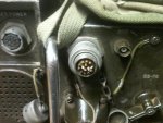
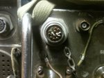
Via 4655 cable and when I removed the cap on the prc I found this
What's wrong here? Am I missing a part?
by the way the radio works fine on its battery.
 
Last edited:

shootist

Member
182
0
16
Location
RI
Ya, I went through 2 tms and Im not seeing anything that has to do with that power connector(besides telling you to connect power cable "here") maybe I need a different tm?.
From pictures I've seen on the net, it doesn't really resemble whats supposed to be there?
I think it should be all female connectors right? to plug into- these appear to be all male?
 

shootist

Member
182
0
16
Location
RI
ok I went through the tms again (they are in pdf format)
on page...there is no page number on it but in the pdf its 110.
Originally it looked liked gibberish had to zoom to 800%
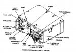
before it was clear- the diagram shows the power connector
when you zoom to 900% you can read a note about the jumper pins
apparently this is a "plug" to use when in back pack config.
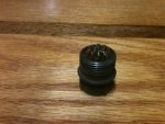
I did some serious yanking and it popped out, and the normal connector is present.
thanks for the "look at the tm again" tip!
The paper ones are sometimes easier to read but the electronic copies
are nice on a laptop in the shop.
here is a pic of the unit removed if anyone is interested
the tm I found it in is: 11-5280-398-12*1965
 

Attachments

Last edited:

OPCOM

Moderator
Steel Soldiers Supporter
3,657
27
48
Location
Dallas, Texas
On the PRC-25, is that what is being discussed? That plug and pins IIRC is the bypass for when the battery is in use and the external amplifier/chassis is not in use. If I am right, leave them alone. The PRC-25 full -35 manual with schematics is avail. unrestricted. The proper cable for that plug, J3, on the PRC-25, will carry those jumper conductors to the mating cable on the amplifier and they will be jumped there.

sorry it's hard to see but it is legible.
 

Attachments

Last edited:

OPCOM

Moderator
Steel Soldiers Supporter
3,657
27
48
Location
Dallas, Texas
opcom thanks for the tip on the burns.
I had read that you need to be a min of
20" from it even when transmitting on low
Due to potential radiation burns says in the tm
Is that possible?

No, that's a bit paranoid. You can pass right by it with no harm but standing right there next to it will give a small dose of RF. The human body (6 FT ) resonates about 40MHz so you make a good 'load' to absorb that power. Just don't stand right next to it for more than a few seconds if worried. Burns only come from touching on these radios. OSHA and various 'nannys' may beg to differ. I've been right next to the ant. with 35W transmitting data and felt no worse for it. Felt nothing. The effect is heating, not nuclear rads. One effect is the body or other materials next to the antenna will detune it. That is the worst thing IMHO the rest is monster stories.

As far as the power up- I have it jumping power to a vrc53
set up so I just wanted to make sure all was
connected correctly and I could fire it up
without the mast sections and not do any damage.
Couldn't find that info in the tm.
It appears for now all is well although I haven't
check the 53 yet.

A VRC-53 is a complete system:
see VRC-53, AN/VRC-53


Best to refer to the components by proper names or others may become confused.

As far as transmitting I can't because
The handset apparently has a visible broken or
Frayed wire in the cord it's a h-189/gr
Couldn't find any online so I just posted
For one in the WTB classifieds
I have another post in this section
Called vic1 and iPod in that I explain
How I have it all set up.
Thanks agin guys for all the help
Be aware the amplifier of the VRC-53 takes 24V in and makes 12,5V and 2.5V for the PRC-25. Don't feed 24v to the PRC-25 or -77 or the magic smoke will come out.

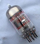
Also the PRC-25, having a wonderful 2DF4 vacuum tube, takes about 0.5 to 1 second to quick-heat. So key it, wait 0.5 second, then speak, or else the first part of the message may not be transmitted because the tube was cold. The -77 is all transistorized. I like tubes.
 

Attachments

Wile E. Coyote

Active member
394
78
28
Location
Lynden WA
forgot pictures sorry
What's happened there is that the shorting plug is still in place for when you use it as a packset, but the top part of the shorting plug has unscrewed, leaving you looking at the wiring *inside* the shorting plug. The caps like to unscrew and fall off, and sometimes people take them off thinking that's how you remove the entire shorting plug.

Anyway, grab hold of the ring on that plug as near to the face of the radio as you can get and twist it counterclockwise. When it comes off you'll be staring at a connector that looks like the one on the AM-2060 in the picture there to the left of the one we're talking about. *Then* you can hook up your RT--->PS cable.
 
Top