• Steel Soldiers now has a few new forums, read more about it at: New Munitions Forums!

  • Microsoft MSN, Live, Hotmail, Outlook email users may not be receiving emails. We are working to resolve this issue. Please add support@steelsoldiers.com to your trusted contacts.

RT524. whats missing?

poof

Dirty Hippie
568
19
18
Location
Wisconsin, Watertown
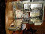
Hello. I did a search.. found this link http://www.steelsoldiers.com/military-radios-other-electronics/6052-rt-524a-demilled.html how ever the pictures arnt there any more.
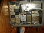
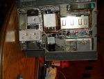
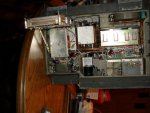
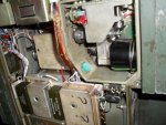
so I took some of my Unit. What appears to be missing?. It powers up and speaker works... will not KEY or Fan come on. have tried 2 diffrent hand sets, stil nothing. and the one component with the ? ? ? on top.. also the 4 prong female (turquoise) round plug.? center of picture. further examination this morning.. I Powered it up with the top off.. I didnt see any GLOW fron the Tube in the top center .. the lights work on the dial.. when I turn on/off and use the circut breaker. then power on again, I hear a kicking noise inside.
Just starting to work on this beast.. would like to have it functional.
am getting the TM's down loaded to disc sent to me in a couple weeks.
what say the experts?


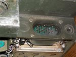
the one PIN was burnt in its past life. I have it able to make contact now a bit of Jerry rig work on the Female side of power plug on mount.
 

Attachments

Last edited:

ke6rwj

creating havoc one broken bolt at a time...
Steel Soldiers Supporter
278
146
43
Location
Alabama
There doesnt seem to be anything missing on the unit from the pictures. The plug J404 is empty on mine and it transmits fine. That module is the Receiver IF amp...

Make sure the mics key on another radio before you assume its the rig, ive been burned by that before... clean contacts etc...

chris
 

ke6rwj

creating havoc one broken bolt at a time...
Steel Soldiers Supporter
278
146
43
Location
Alabama
did you get the manuals? they are available online if you search... there are some troubleshooting flowcharts to go through that...

so i take it its not blowing the circuit breaker (light stays on)?.

does it receive at all, anything? Just to be sure, make sure the XMODE switch in the back is in the NORMAL position. I dont think it has anything to do with this issue, but ive overlooked it before..

bottom of the radio, open the panel to the right, near the hinge..

Chris.
 

poof

Dirty Hippie
568
19
18
Location
Wisconsin, Watertown
I am Fred Flinstone here.. only have dial up service.. so down loads are Right Out.
but I have some TM's on the way.
The power stays on.. dosnt kik the breaker./power off
I will look for the Xmode switch... later... just went to go and do it and the wind closed the door pannels of garage door and pinched the heck out of my finger tips.. as the door closed... When I get done wipeing the Tears of pain and stupidity.. I will check it out. "oh the Pain. the pain.". in my best DR.Smith voice
J.P.
 

dragonman

Member
176
1
18
Location
Mason city, Iowa
I have a bunch of these, they all are missing the tube that is under the sliding cover at the rear of the radio marked "danger high voltage". Slide it to the side and see if you can see it or an empty socket.
 

jwaller

Active member
3,724
19
38
Location
Columbia, SC
you should send it to my person who repairs these units. without proper tools and such, getting one to work properly is impossible. he will treat you right and make sure it transmits on the proper channels.
 

poof

Dirty Hippie
568
19
18
Location
Wisconsin, Watertown
dragonman the tube is next to that amplifier with the sliding cover.. and that is the tube i am refrencing as "NO, ZERO Glow from tube" ...

ke6rwj i took off the cover and the lines on that switch were lined up with X-MODE.. I switched it to normal.. no diffrence...
I have never heard any reception of any thing but Gray Noise.. should i try again with it out of X-MODE now?

jwaller.. in the end i may have to do that.. but for now trouble shooting it with some help is the direction I need to go...
shipping it 2x plus any repair cost and factor in the posibiliy of more damage from shipping.. it might be cheeper to find another unit working face to face deal in the future..
There is still no light comming from the Vacuum tube ..

J.P.
 

OPCOM

Moderator
Steel Soldiers Supporter
3,657
27
48
Location
Dallas, Texas
The big tube generally does not glow, it is ceramic and metal. The tubes are fired up when the mike is keyed, beware 700 volts on that tube which is efficiently deadly. The large output tube is a 7843. The driver, which is what you see in the top center, is a 5686. The anode (pin 7) of the driver will have 200V or 290V on it during transmit. You can check for these voltages with a -good- DC meter. Beware cheapies may not be rated for more than 600VDC. beware bad test probes and leads. At 700V the voltage can arc a little and get you. I am not preeaching, I just don't know if you have experience with high voltage electronics and I don't want to see a fellow VRC-12 owner get shocked. So enough of that.

Steve Haney TC0654@mesh.net will fix the radio and align it for you. I trust him with the highest confidence and he is as honest as the day is long. He does mine when I cannot fix them myself. If you want, he might sell you the connector if he has one. I bet he does.

Be aware it has three miniature 6205 tubes in the front end. These generally are trouble-free and run on 105VDC during receive. The A1600 module is supplied by 25.5VDC (pin eight) and converts this to 105VDC (pin 9). GND is pin 10. Check to see if the module is supplying the 105V when the unit is ON and in receive mode, even with static.

Each pin on that burned connector has a letter.
What is the letter next to the burned pin?
I will be glad to read the wiring diagram and advise.

demill on these is usually a missing module or a torch hole right into the chamber where the large tube is. If that pin is burned there is a reason. Keying the mike ought to result in a large increase in your 27.5V power supply current to about 4-8A and the sound of a blower spooling up. It is not good to key it with no antenna or dummy load, but for a second on LOW power it won't hurt it.

The manuals with enough info to do detailed troubleshooting and allow technical repair beyond replacing the modules and tubes themselves are still restricted. They are 424 and 612 pages. It is interesting reading and well worth the study of the theory. These are the ones you want:
TM 11-5820-401-34-2-1
TM 11-5820-401-34-2-2

I legally have the manuals, but I won't copy or distribute them. I will gladly try to help you fix the radio while you wait for your manuals. It might be a simple thing after all.
 
Last edited:

Westech

CPL
6,104
207
63
Location
cow farts, Wisconsin
poof I know it did recieve we would listed to the mexican TV channel and other chatter on post. The main power pin got burned for what reason I have no idea, but it still Recieved after that.
 

poof

Dirty Hippie
568
19
18
Location
Wisconsin, Watertown
looking at the female recepitcal the burnt pin would align with the A hole...... hahaha ( i said A-Hole)

the male pin area is scorched and I cant read / see any letters there any more.

what dose having it in X-MODE do to the radio?
is there any close up pictures of any areas that might help diagnose? i can take them
is there any capaciter in these? that might store power and light up my life, when out of the power mount?

Thanks.
and thanks for chiming in Westy..
hope you all can swing by here for Poof-fest.
 

OPCOM

Moderator
Steel Soldiers Supporter
3,657
27
48
Location
Dallas, Texas
The pin A is ground. This is very important that there be a good ground connection from the radio case to the (-) power source, the main power ground. Are you using the mounting tray with integrated socket that radio's plug fits into? For test you might want to use a strap or a #12 wire from the case to the (-) side of the supply, just put lugs on the wire ends and use an existing screw on the radio case and one on the mount to do what the burnt off pin would.

B is the high current pin for battery input, required.
J is a 25.5V input, direct from the battery or externally switched via a remote head attached to the mount. The jumper/voltage has to be there to activate the coil for the power relay when the power switch is turned on. The mount should provide this depending on a jumper inside the mount, which is almost always set to do the correct thing for stand-alone. On the mount, pins B and J ought to have the (+) battery voltage. Thinking about this, the ground pin being burned off, this might happen if the power wires to the mount, (+) and (-) were reversed and the radio was slid in under certain circumstances such as with the mount and radio not grounded except through the antenna cable or another high-current ground. would be a direct short of the battery.
 

poof

Dirty Hippie
568
19
18
Location
Wisconsin, Watertown
The pin A is ground. This is very important that there be a good ground connection from the radio case to the (-) power source, the main power ground. Are you using the mounting tray with integrated socket that radio's plug fits into? For test you might want to use a strap or a #12 wire from the case to the (-) side of the supply, just put lugs on the wire ends and use an existing screw on the radio case and one on the mount to do what the burnt off pin would.

B is the high current pin for battery input, required.
J is a 25.5V input, direct from the battery or externally switched via a remote head attached to the mount. The jumper/voltage has to be there to activate the coil for the power relay when the power switch is turned on. The mount should provide this depending on a jumper inside the mount, which is almost always set to do the correct thing for stand-alone. On the mount, pins B and J ought to have the (+) battery voltage. Thinking about this, the ground pin being burned off, this might happen if the power wires to the mount, (+) and (-) were reversed and the radio was slid in under certain circumstances such as with the mount and radio not grounded except through the antenna cable or another high-current ground. would be a direct short of the battery.
Tomorrow I will do some checking of voltage at those mentioned pins.
IF / Lets assume that the power was crossed like you have said, above in red. sounds very plausable to have happened.
What would be the resulting Damage , other than the Pin being burnt off/out
what component insid would have failed or taken the hit? and now need replaced.?
J.P.

ETA. yes its sitting in my M151a1 in a new MT1029 with cable that go's to the battery
 
Last edited:

Wile E. Coyote

Active member
392
75
28
Location
Lynden WA
Very likely the power wiring is haywire as OPCOM suggests. I don't have my manual handy but I think there's also a heavy-current diode in the 524s that shorts if the voltage spikes or is reverse-polarity, so if the power switch were turned on when you slid the radio into the tray with the power-wires reversed - KAPOW - something will try a bit of unintentional arc-welding. Been awhile but I think I had one short once after a voltage spike when my bench power supply regulator figured it was time for early retirement. Replaced the diode with one someone kindly mailed me for free off one of the collectors lists and voila! Back up - no short.
 
Last edited:
Top