• Steel Soldiers now has a few new forums, read more about it at: New Munitions Forums!

  • Microsoft MSN, Live, Hotmail, Outlook email users may not be receiving emails. We are working to resolve this issue. Please add support@steelsoldiers.com to your trusted contacts.

SEC12 on milemarker hydraulic winch plate.

Coug

Well-known member
Steel Soldiers Supporter
2,953
4,298
113
Location
Olympia/WA
EDIT: I'm doing this mostly because I haven't seen much of anything about doing this type winch with the milemarker plate. Most of what I read basically stated that you either need the A2 plate and the extensions to do an electric winch, or other stuff like that. Figured I'd document what I did/found in order to help out the next guy.


As the title says, I'm installing the 24V version of the SEC12 milemarker electric winch into the mounting plate for the hydraulic winch.
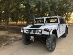
My truck is a model M1123, so an A2 truck.

I skimmed through the hydraulic winch install instructions, and the main pieces of information I found there relevant to this install is that the lower control arm bolts need turned around so the nut is facing forward, and that to accomplish this the driver's side brake caliper and brake rotor have to be removed. Not a huge deal; anyone that owns one of these trucks should have been under there to at least check torque on the halfshaft bolts.

I'm not done with the install yet. So far just have it mounted to the plate and the plate installed.

Tools used so far" 1 1/8" wrench and socket for lower control arm bolts.
15/16" wrench and socket for the bumper bracket bolts.
3/4" wrench and socket for the front shackle/bumper bolts.
9/16" wrench for brake caliper bolts.
10mm 12 point socket for the Blue Hummer locking halfshaft bolts I have installed. If you have regular bolts there you'll need to buy a new set of them and red locktite as they are single use only (torque to yield tightening method)
8mm allen wrench for the winch mounting bolts (it came with some grade 8.8 bolts; I decided I'd rather have grade 12.9 and the local hardware store only had them as socket head cap screws.
Torque wrench (3/8 drive) for the halfshaft bolts and winch bolt tightening.
27/65 drill bit (and several smaller sizes as well, but size not critical on them)
1/2x13 tap.

snap ring pliers to remove the end rollers, not actually necessary for install just made life a little easier.
work light
flashlight

Hardware I bought:
4 10x1.5 by 35mm allen head cap screws in grade 12.9 for winch mounting.
4 hardened 10mm washers (grade 12.9, left over from another project)
2 1/2x13 bolts and nuts. Nuts stacked on the bolts to reduce reach. I think the bolts are 1" long, might only be 3/4" Will be changing them out for 1/2" long bolts if I can find them and washers for the spacing.

Main things that I've had to modify so far.

Driver's side front mounting bracket. The winch has one little bolt head sticking out just enough to cause issues. Solution is to grind/cut a little bit of the lower corner of the bracket off. Takes at most a couple minutes.
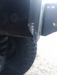
e93579961cc1f9480071f0026e0128247373f660-2.jpg

NOTE: when installing the brackets, the angled brace faces up. It will NOT fit the winch if it's facing down (true of any winch install)


Next issue, using the original mounting holes, the body of the winch is right up against the front plate. There is zero room for bolts/nuts to mount the roller fairlead plate on there.
Solution: the roller fairlead came with 2 sets of holes. Some 10mm or 3/8" sized holes that are a little offset, that match up with the original holes in the mounting plate for the roller fairlead, and a second set of holes centered in the plate 1/2" diameter.
My solution was to drill and tap a set of 1/2" holes for mounting it. I don't have any bolts short enough at the moment, but the ones I'm using seem to fit perfectly.
picture of the backside where the sinch body would be; you can see the bolts just barely stick through.
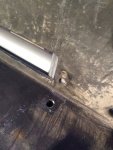
e93579961cc1f9480071f0026e0128247373f660-3.jpg
Front side, not tightened down yet, and actually the roller fairlead is upside down in the picture as the smaller holes match up to holes already in the place nearer the edge.
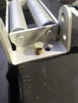
e93579961cc1f9480071f0026e0128247373f660-1.jpg


So that is where I am at for the moment. Tomorrow's job will be to sort out the wiring to the winch. I'll also try to take a few pictures of what it looks like installed. There is plenty of room to fit my hand in there to work the clutch lever. Just have to figure out a good place for the control box mounting. At the moment it's getting installed on the outside of the winch plate until I get a good cable crimper to make some longer cables.


As for cost, so far the winch (15% discount right now from milemarker) was just under $800, and another $90 for shipping.
the 24V are apparently special order, even though they stock them, so they cost a little more than the 12V version.

The mounting plate and brackets were hand-me-downs from one of the other guys in this area. I got really lucky with that.
 
Last edited:

TNDRIVER

Well-known member
Steel Soldiers Supporter
332
507
93
Location
Cleveland,TN
As the title says, I'm installing the 24V version of the SEC12 milemarker electric winch into the mounting plate for the hydraulic winch.
My truck is a model M1123, so an A2 truck.

I skimmed through the hydraulic winch install instructions, and the main pieces of information I found there relevant to this install is that the lower control arm bolts need turned around so the nut is facing forward, and that to accomplish this the driver's side brake caliper and brake rotor have to be removed. Not a huge deal; anyone that owns one of these trucks should have been under there to at least check torque on the halfshaft bolts.

I'm not done with the install yet. So far just have it mounted to the plate and the plate installed.

Tools used so far" 1 1/8" wrench and socket for lower control arm bolts.
15/16" wrench and socket for the bumper bracket bolts.
3/4" wrench and socket for the front shackle/bumper bolts.
9/16" wrench for brake caliper bolts.
10mm 12 point socket for the Blue Hummer locking halfshaft bolts I have installed. If you have regular bolts there you'll need to buy a new set of them and red locktite as they are single use only (torque to yield tightening method)
8mm allen wrench for the winch mounting bolts (it came with some grade 8.8 bolts; I decided I'd rather have grade 12.9 and the local hardware store only had them as socket head cap screws.
Torque wrench (3/8 drive) for the halfshaft bolts and winch bolt tightening.
27/65 drill bit (and several smaller sizes as well, but size not critical on them)
1/2x13 tap.

snap ring pliers to remove the end rollers, not actually necessary for install just made life a little easier.
work light
flashlight

Hardware I bought:
4 10x1.5 by 35mm allen head cap screws in grade 12.9 for winch mounting.
4 hardened 10mm washers (grade 12.9, left over from another project)
2 1/2x13 bolts and nuts. Nuts stacked on the bolts to reduce reach. I think the bolts are 1" long, might only be 3/4" Will be changing them out for 1/2" long bolts if I can find them and washers for the spacing.

Main things that I've had to modify so far.

Driver's side front mounting bracket. The winch has one little bolt head sticking out just enough to cause issues. Solution is to grind/cut a little bit of the lower corner of the bracket off. Takes at most a couple minutes.
View attachment 845823

NOTE: when installing the brackets, the angled brace faces up. It will NOT fit the winch if it's facing down (true of any winch install)


Next issue, using the original mounting holes, the body of the winch is right up against the front plate. There is zero room for bolts/nuts to mount the roller fairlead plate on there.
Solution: the roller fairlead came with 2 sets of holes. Some 10mm or 3/8" sized holes that are a little offset, that match up with the original holes in the mounting plate for the roller fairlead, and a second set of holes centered in the plate 1/2" diameter.
My solution was to drill and tap a set of 1/2" holes for mounting it. I don't have any bolts short enough at the moment, but the ones I'm using seem to fit perfectly.
picture of the backside where the sinch body would be; you can see the bolts just barely stick through.
View attachment 845824
Front side, not tightened down yet, and actually the roller fairlead is upside down in the picture as the smaller holes match up to holes already in the place nearer the edge.
View attachment 845825


So that is where I am at for the moment. Tomorrow's job will be to sort out the wiring to the winch. I'll also try to take a few pictures of what it looks like installed. There is plenty of room to fit my hand in there to work the clutch lever. Just have to figure out a good place for the control box mounting. At the moment it's getting installed on the outside of the winch plate until I get a good cable crimper to make some longer cables.


As for cost, so far the winch (15% discount right now from milemarker) was just under $800, and another $90 for shipping.
the 24V are apparently special order, even though they stock them, so they cost a little more than the 12V version.

The mounting plate and brackets were hand-me-downs from one of the other guys in this area. I got really lucky with that.
Can not tell from your write up if you have already pulled the a arm bolts, if not once the nuts are loose it helps to spin the bolt back and forth with an impact wrench for a few seconds to loosen it up, they come out much easier. You will need the snap ring pliers to remove one of the rollers to get the swedged end of your cable thru, been there done that.
 

Coug

Well-known member
Steel Soldiers Supporter
2,953
4,298
113
Location
Olympia/WA
Can not tell from your write up if you have already pulled the a arm bolts, if not once the nuts are loose it helps to spin the bolt back and forth with an impact wrench for a few seconds to loosen it up, they come out much easier. You will need the snap ring pliers to remove one of the rollers to get the swedged end of your cable thru, been there done that.
Yes, I've already done the A-arm bolts.
I used a farm jack to lift the tire off the ground slightly, and that relieved enough pressure off of it that I could tap it through using a brass drift punch and a hammer. I didn't mention those tools in the list above because:
A) I forgot
B) not really necessary.
Once it's loosened up a little I could use my hand on the socket and spin it out by hand. It takes a while, but the impact gun wouldn't fit in there.

I think at one point I also used the socket as a hammer (the 1 1/8" socket I have been using is a deep well impact, so lots of mass)

I did mention snap ring pliers to remove the rollers, but on my cable end it wasn't required to remove the rollers for the cable to fit, as it's already wide enough.
 

Coug

Well-known member
Steel Soldiers Supporter
2,953
4,298
113
Location
Olympia/WA
467262efa19dd495ac069b4f23fe5cbadb48d50d-1.jpg
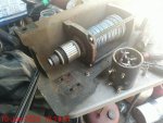
control box is just there until I get the wiring sorted out. There really isn't a good place to install it at the front of the truck near the winch, and I'm almost certain I will have to extend the wires for the control plug.

Plenty of space to reach in there and operate the clutch mechanism. That was one of the reasons I decided to go this route instead of just bolting it to the A2 bumper plate, because I couldn't see any easy way to access the lever except from below, and that seems like it wouldn't be the easiest places to get to if I was buried in mud or snow or something like that.


edit:
Only additional tools used so far for the wiring are:
5mm allen wrench (mounting the control box)
13mm combination wrench for attaching wires to the winch motor.

used a 1/4" drill bit to drill 1 additional hole for installing the control box in it's current location, but as it is temporary it's not needed.


Additionally, I now have 2 15 foot chunks of 2 gauge welding cable and appropriate end pieces on order, as well as a 300 amp circuit breaker on order to wire the winch directly into the battery box. I do realize that I can go straight to the starter motor connections, but there isn't anywhere down there to mount a breaker (unnecessary I know but I am slightly paranoid when it comes to unprotected wiring) and the eyes on the existing cable ends are too small.

As for the 2 gauge size, I did some searching and that appears to be the standard size used for most 12V winch installs of any size on full size trucks. It's not rated to handle 100% continuous duty with heavy loads, but then neither is the winch. Being 24V instead of 12V, at 100 max load I'm only pulling in the 185 amp range, so the wiring shouldn't be an issue. (in welding applications it's rated to 250 amps for 25 feet of run and 200 amps up to 50 feet of run)

Just more things to consider.
 
Last edited:

Coug

Well-known member
Steel Soldiers Supporter
2,953
4,298
113
Location
Olympia/WA
So an update:
Between rain showers I was able to get some wires made up and installed.

Running the positive cable from the battery box (through 300 amp breaker) along the top of the frame rail to the front of the truck.
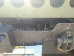
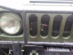
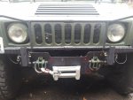
I removed the contactor assembly from the milemarker plastic covered box thingy (really just a cover, doesn't seal anything out) and bolted it to the front grill on the inside.
1ff557dbce25c48fd9fcfc91c4d887a22d2c35a7-2.jpg

I took the remote plug and made my own wires for it, as the ones they used are teeny tiny wires.
I didn't take a picture of it, but their waterproofing job on the back of the plug was crap. Probably not actually meant as waterproofing, but to hold the wires into the plug back. They used some ferrules to make the wires actually clamp into the back of the plug, but none of the screws that clamp down to hold them were particularly tight. Once I pulled the hot glue holding all the wires together to the plug, it took very little effort to pull the wires out.
I replaced all the wires with 14ga prestolite wire and have the plug dangling off to the passenger side behind the brush guard until I decide what I want to actually do with it.

The eyelet on the end of the negative cable was just slightly too small to fit onto the ground stud of the starter (I don't expect to ever use the starter AND the winch at the same time, so I see no reason not to ground the winch there).
I cut off the end of the cable and was going to just crimp a larger eyelet onto it, but the cable is 4ga, and my eyelets are 2ga. So I made up a 2ga ground cable for the winch (I had the cable already, but thought I would try to just use the one that came with it instead)

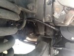
Wasn't a good place to run the ground cable from where it was at, so it's going out the passenger side of the winch plate, then zip-tied it to the brake line, passed inside the front suspension brackets, and followed the transmission cooler lines to the starter.
One thing I've noticed is a lot of the electrical connections have a small wire eyelet between the large cable eyelet and the load. That's something I was always told not to do, as you want the heavy electrical loads to not have anything in the way.
1ff557dbce25c48fd9fcfc91c4d887a22d2c35a7-1.jpg

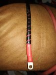
Anyway, I used a hydraulic crimper for the cable ends, then adhesive lined heat shrink. Then wrapped them in protective sheathing because I'm minorly paranoid about electrical shorts. Did it with the ground cable also.
1ff557dbce25c48fd9fcfc91c4d887a22d2c35a7-3.jpg

Eventually I will get around to replacing the wires between the contactor and the winch motor with 2ga as well so all the wiring matches in size and type. I'm using welding cable so it's a bit more flexible than the original.
 

Coug

Well-known member
Steel Soldiers Supporter
2,953
4,298
113
Location
Olympia/WA
Just felt I should mention again a couple highlights.

The winch came with 4ga cables. Not saying this is good or bad, but it is what it is. Probably more than good enough considering the 12V winches come with 2ga and run at twice the amps.

their remote uses some type of chinese plug that's "waterproof". I did some searching and found the company and type of plug, but unable to find them on the market. I will probably end up replacing it with something more standard in the future (or just do a wireless type remote)

The original wiring for the remote is tiny. I might have broken one of the eyelets on the end of the wire where it connects to the contactor. Maybe not, but hard to tell when the shrink wrap is more substantial than the wire or eyelet metal.

One of my hood hinges was a little forward compared to the other. When the hood is raised one of the carriage bolt heads that retains the grill screen was contacting the winch plate, making opening the hood the last few inches difficult. I knocked out the hinge pin, loosened the hinge plate, slid it back 1/8 or 3/16", and no more issue.

There is no good place to put the contactor. I suppose I could buy more wiring and install it in the space by the battery box where the slave cable mounts (especially with the 2ga cable instead of 4ga) and then could do the plug for the remote above the slave cable, but that's more work than I felt like doing. I'm not a perfectionist; I just want stuff to work when I need it to, and not look terrible.

There isn't really a good place to mount the circuit breaker in the battery box. I have enough room because I'm running group 24 batteries. If I had the 6T batteries in there, I don't know where I would fit the breaker. I also have a MEGA fuse holder and a couple 300 amp slow blow fuses for it on the way because I'm not sure how much I trust the breaker yet, but I definitely want something in there just in case of a short circuit.
 

Coug

Well-known member
Steel Soldiers Supporter
2,953
4,298
113
Location
Olympia/WA
So I got asked in a message if this mounting plate works with the A2 style brush guard. I would also like to know this before I go and spend $500 for that style brush guard in order to regain my teardrop shackles in the front (they just seem stronger to me than the D-ring type shackles that mount the winch plate)

So can someone confirm the holes I circled below are the ones for the A2 brush guard mounts?

1ff557dbce25c48fd9fcfc91c4d887a22d2c35a7-4-1.jpg

EDIT: I compared it to the A2 bumper I took off, those holes are in the same place so I would expect it to work; just hooping to verify.
 

Coug

Well-known member
Steel Soldiers Supporter
2,953
4,298
113
Location
Olympia/WA
Thanks, I appreciate it. Now just to get around to finding one at what I consider a reasonable price.
 

Coug

Well-known member
Steel Soldiers Supporter
2,953
4,298
113
Location
Olympia/WA
At 2.5 years old, or half a year past the warranty, the winch stopped working. Finally determined it's an internal motor issue, and took it all apart.

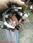
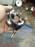
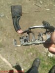
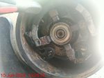
Brush holder is rusted from moisture intrusion (so much for being rated as "Waterproof")

brushes themselves are in excellent shape, and 2 of them are soldered directly to a bar, so not able to be easily replaced..

a before picture. I had already freed up some of the brushes. The brush on the top is the position all of them were stuck in when disassembled.
5b9be2badc8a3ce31272e0294203bd8cb08e4c78-9.jpg

and another angle

5b9be2badc8a3ce31272e0294203bd8cb08e4c78-7.jpg

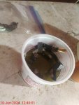
plastic container with muriatic acid. It only took a few minutes to get most of the rust off. I also used a small file as well, then soaked again, and finally rinsed off then used electrical contact cleaner to remove the water. After that was about 3 minutes in the air fryer set on "dehydrate" which is 120 degrees heat, and it was completely dry.
5b9be2badc8a3ce31272e0294203bd8cb08e4c78-4.jpg

a lot cleaner, but not perfect. This was after the first 5 minute soak in the acid. I checked and muriatic acid (diluted hydrochloric acid?) will dissolve copper, so I was being careful. Can definitely tell the difference between where the acid was and where it wasn't.
5b9be2badc8a3ce31272e0294203bd8cb08e4c78-1.jpg
5b9be2badc8a3ce31272e0294203bd8cb08e4c78-6.jpg

reassembled the brush assembly and back in the motor case
5b9be2badc8a3ce31272e0294203bd8cb08e4c78-8.jpg

The hardest part was getting all the brushes pushed into their holders far enough to slide it on. I ended up using 2 small screwdrivers to hold 2 of the brushes, and used my hands for the other two. I still felt like I needed more hands.
5b9be2badc8a3ce31272e0294203bd8cb08e4c78-2.jpg

That was all the pictures I took.

The rubber o-rings they use to seal up the motor assembly are a joke. Maybe a little over a millimeter diameter. The one on the drum end was just supposed to sit in a wide groove for the motor assembly against the case and didn't have an actual groove that I could see, so I used some sealant there instead. Just enough that it barely pushed any out when tightened down. The other end had a small groove, and didn't appear to have any moisture intrusion past it so I reinstalled as is.

I also took off the cover for the gearing and checked it out; no signs of water, but it was also closed with 8 small bolts and a real gasket. The aluminum of the case is corroding around the screws (stainless screws and aluminum don't like each other much) so I cleaned the powder a bit, and used some marine anti seize on the machine screws during reassembly.


Anyway, it's back assembled and worked how it was supposed to, but now have a new project to work on; the driver's side front brake caliper mounting bracket is loose and needs tightened down, like I've had to do with the other 3 (so not unexpected) as well as brake pads for both front brakes (I have all the parts, just not the ambition. Need to get it done in the next week and a half before I take it on a trip.
 
Top