• Steel Soldiers now has a few new forums, read more about it at: New Munitions Forums!

  • Microsoft MSN, Live, Hotmail, Outlook email users may not be receiving emails. We are working to resolve this issue. Please add support@steelsoldiers.com to your trusted contacts.

Suggestions for mounting a MEP802a on a trailer

Humpy

New member
62
1
0
Location
Springfield, South Carolina
Found a very nice trailer at a very good price on Craig's day before yesterday that was a new posting and yesterday I went to get it. Lucked out big time, I got there and after I paid him and hooked it up we were talking and he said he got another call from a guy in NC who said he was coming to get it a couple minutes after I told him I was on the way.

Extremely well made trailer and the guy hauled big Harleys and Hondas on for years . It is about 47 1/2" between the angle rails and 9 feet 9 3/4" long on the bed. The axle is about 3 feet from back end so I will mount the MEP for CG over the axle.

Does anyone know where the CG is on a 802a?

The PO said the wood floor finally gave up about 9 months ago and he replaced it with a piece of aluminum star plate.

While running the 802 sitting on my cargo trailer I noticed it vibrates the whole trailer but it can't move now as I have 2X6s screwed to the deck to keep it from moving while bring it from Ft. Bragg.

Obviously setting it on the aluminum star plate the skids are gonna do a number on the plate and most likely allow it to slide unless it is secured The star plate is only about 1/8" and the cross members under it are multiple C channel stock.

I am thinking two possible options, first is to get two 2X6X8ft and mount the gen to them with carriage bolts and secure it with chain binders like is displayed on the data plate on the side for flat car transport.

Next option is 3/4" stall mat from Tractor Supply made from ground up car/truck tires. They are 4X6 so large enough. Tough enough not to compress and not that expensive.

Another option is get a 3/4 piece of plywood and overdeck the back 8 feet of trailer, secure it with carriage bolts and bolt the plywood to the outer rails of the trailer.

The trailer frame and cross members are fabricated from 4" C channel. On top of that is angle 3" wide and 2" high and welded together. It has four eye bolts the PO secured Road King Harleys and Honda Gold Wings (800/900 lbs respectively) and he covered the US from midwest (Michigan/Iowa/Texas) hauling them to SC for rework and back for delivery. He estimates he pulled the trailer 20,000 miles with these bikes tied down so the generator weight should not be a factor.

The trailer has a axle with leaf springs and rides quite smooth with no load. The design is very well done and has the nicest brake/tail light housings I have ever seen and came with tractor trailer sealed lights in the rubber donuts which is what I have on several other trailers I own. They are completely enclosed and large enough to store replacement sealed bulb assemblies inside should one fail on the road.

There is also a nice heavy duty tilt down ramp that is removable. Also there is a channel fabricated from steel star plate for the bike wheels

At any rate I am open to other suggestions as I am sure a number of folks here have mounted big units. Not planning for it to be on the road that much (like it has been) but want to be able to back it into my shop where it will be protected from the elements and in the event of an emergency open the door, hook it to car/truck, pull it up to the wherever needed from home use to my volunteer fire dept use. We have gens on a rescue truck for scene lights/tools but not designed to be tied down for long term use.

Will see about posting some pics after while. Thanks yawl.
 
Last edited:

DieselAddict

Well-known member
Steel Soldiers Supporter
2,486
1,890
113
Location
Efland, NC
The CG favors the engine end a few inches ahead of the center of the skid. I wouldn't worry too much about where it is on the skid since the real goal is to have at least 10% of the total weight of the setup on the tongue. Get the generator on there and slide it around till you have enough on the tongue. On my setup it is bolted in the standard location and its too light in the front. Its not exactly unstable but I can tell when towing at highway speeds that it wants to wiggle more than I would like as it encounters undulations in the pavement. I'm going to be doing some work on my setup and will be rebalancing everything in the process.

I like the idea of using the recycled rubber mat. I would cut it into strips and put one under each skid then bolt it through to the aluminum deck. If you can get it bolted through the deck and into the trailers frame that would be even better. If not put some kind of rigid plate between the skid and the aluminum deck to give the aluminum more support and spread the forces out a bit.
 

Ray70

Well-known member
2,407
5,219
113
Location
West greenwich/RI
It might not be necessary, but maybe put a second piece of the 3/4" mat under the deck with a reinforcing plate around the bolts then double jam nut the bolts just snug?
In other words put your bolts through a piece of mat and the reinforcing plate that DieselAddict mentioned, to isolate the bolts from the bottom of the deck and allow more vibration dampening without putting stress on the aluminum decking. Just a thought....
 

1800 Diesel

Member
768
25
18
Location
Santa Rosa County, FL
I'm with Chris on the recycled mat--we use old tire carcasses (retrieved during road trips) and then the treads are cut into rectangles 5 1/2" wide and in lengths as needed to span the mounting bolt patterns. These are placed on top of treated 2x6s that are through-bolted through the trailer cross frames if possible. 2x6s should span the next frame past each end of the generator skid by at least 4" or so (at forward & aft ends).

Galvanized carriage bolts are used to bolt the generator & the 2x6s. For added padding I've also installed the rubber on both sides of the 2x6, with the lower pieces being cut 6 or 8 inches wide (slightly wider than the treated wood size).

For the MEP-002A & 003As, I've also used old shock absorber bushings & large flat washers at each end of the mounting bolts so the generator frame is not actually hard-mounted to the trailer. This shouldn't be necessary on the 800 series sets though.

Also something to consider regarding the CG. If you plan on installing an auxiliary fuel tank on the front portion of the trailer, consider the tank & fuel weight in the equation for locating the final position of the generator. It's always good to have at least 50 gallons on a trailer-mounted unit or so for extended run times beyond just a day, but this added weight needs to considered.

Kevin
 
Last edited:

Chainbreaker

Well-known member
1,750
1,845
113
Location
Oregon
Some good suggestions using stall mats and future CG considerations for a potential auxiliary fuel tank installation.

FYI - I mounted a 35 gallon Home Depot "Better Built" tank up front on my M116A2 trailer and two Jerry Cans. The problem now is that I have to use a High-Lift jack to raise the tongue of the trailer whenever I need to hook up, especially when fully fueled (need to install trailer jack so I can raise front landing leg). Before mounting the aux tank I could lift the front tongue by myself as the CG of the MEP-002a was fairly neutral (slightly forward of axel) on the trailer. You trailer sounds fairly long but depending on your trailer geometry, and if your trailer doesn't have one, you might also want to consider installing a rear stabilizer leg(s) so there is NEVER any chance of the teeter-totter effect when unhooked especially if you add any stuff later that might shift the CG (including yourself stepping onboard rear of trailer with heavy objects in hand).
 

Humpy

New member
62
1
0
Location
Springfield, South Carolina
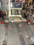
Gen 2 pics.jpg Double click on pic to get it to max size. Bed is 9'10" long and about 47" wide between the outboard rails. Ramp in back designed for Honda Gold Wings and full dress 74 Harleys to be driven onto trailer. The black stripe down the middle is the crud under the wheel channel. The piece of wood is for kick stands and has been removed. Note large center channel on tongue. I believe that was a shaft alley for a PTO drive. There is 6" channel from bottom of hitch all the way back to the axle and I thought I was going to have to reinforce it ! !

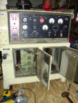
Well first off I decided to repack the wheel bearings yesterday as I figured do it while the weight is off. On the data plate on the unit the CG is identified and for us good ole boys even has a picture of where it is haha.

Unloaded it and it is definitely tongue heavy but manageable by one guy. I estimate 100 lbs of tongue weight now. It tows like a dream. In looking over the frame it is light but well designed for strength. Some of the "C" channel is also formed into a long taper. Pictures will tell the tale when I can get some.

Wow did I get a education after I got under it. The underside is John Deere green and I can tell a whole bunch of stuff has been removed but the kicker there is two mounted cable pulleys at the rear mounted dead center so steel cable can be routed left and right from the middle. I figure this had to be part of a manure spreader or hay bailer????

The axle is also JD green and bearings are 1" ID so are heavy. Grease had started to break down so off they came for a thorough cleaning and repacking with Grease Aircraft WTR. 4 Lug axles and I checked 1" spindles with 1" ID bearings on 4 lug pattern are rated at 2000 lbs.


Now here is the tricky part, the axle springs (front and back) are mounted up inside pockets that are part of the chassis ! ! ! Never saw anything like this. It is like the design would tend to support the leaf springs from side movement ????? Obviously they are not touching but a side deflection of perhaps 1/4" they would be contacting.

The guy that reworked this thing boxed in the "C" channel tongue arms and welded them. The middle section seems to have been a shaft alley in its past life. Then he went "belt & suspenders" and added a six inch wide "C" channel down the middle all the way to the axle cross members ! ! ! ! ! !

The "C" cross members just forward and rear of the axle have a heavier construction as well.

I am heading to lumber yard this morning and getting a 3/4" piece of plyform and picked up 1/2"X3" carriage bolts yesterday with two nuts for each.

First off I am going to trim the plywood just enough put the whole sheet on the front part of the trailer and measurements indicate the CG of the Gen will still be on plywood mounted right over the axle. Will remove the ramp supports and eye bolt and mount the whole piece of plywood and remount the the eyebolt/ramp supports through the plywood.

Next I will make up hoist slings so I can pick up and hold generator and move the trailer under it to get the tongue weight where I want it. The plywood will be secured with bolts into the 3" base of the angle all the way down the sides and across the front of the chassis. This is going to leave about four feet of storage area forward of the generator for fuel cans.

The diamond plate is very thin and useless for any rear support. I can walk on it but it is mainly used for gripping.

Before I drill the holes for the carriage bolts I will secure generator with 2X6s screwed on the sides and front and use my ratchet cargo binders as well. Then will get out and pull it to make sure there is no "tail wagging the dog" effect. I too hate that in a trailer.

The game plan is to allow for me to pick up the tongue and set it on ball and I am figuring maybe 150 lb tongue weight with the 3/4 plywood on the front part of the trailer which I can handle and once mounted add the fuel cans so I figure I can get mobile with about 80 gal of off road diesel to feed it.

Also thinking of running conduit and adding 120V weatherproof outlets maybe three on each side and having them wired into the lugs and on the end a 240V 30 amp plug. That way I can put trailer in middle of a scene as well as have the capability of running a remote plug in panel away from it into a structure for ham radio emergency commo.

I found a old tractor exhaust stack that is about 42" long and I have a piece of 1 1/4" pipe joint welded to it so I can screw it to the exhaust outlet and raise the exhaust outlet about 10 feet in the air and direct it radially as desired.
 
Last edited:

Humpy

New member
62
1
0
Location
Springfield, South Carolina
Went up to lumber place today and got a sheet of 3/4" treated exterior plywood, came home and stripped some hardward off the trailer. Stamped on plywood allow 1/4" expansion on long sides so I trimmed about an inch off it. Then I had to relieve four places each side for bolt heads that hold on fender and tail light housings and it popped right in.

When I got to lumber yard (45 miles) I felt the hubs and both were cold so the Grease Aircraft WTR was doing just fine.

Next I made up cargo slings. Ones I had made were too long so I hooked one up and determined what I thought he ideal length to be and came up with 60" end to end on the loops. Pulled out a spool of OD nylon strapping and cut four of them 70" long and marked them 10" from the end and used my industrial sewing and harness machines to make them up. After I made them up I hooked them to a 3/4" bolt clevis D shackle. On the other ends I used the chain quick links that screw together up to 3300 lbs.

After I got it ready to be lifted I got the backhoe out and pulled it around and hooked to it. Wind was blowing hard and when it came off first trailer the wind turned it 90 degrees so I had to get a tie down strap and hook it to gen and pull it around so it would be sitting right.

I did not have anyone to direct/control so I basically just set it on the trailer so I could get it in my shop as I did not want to leave it outside any longer.


The CG of the gen is about 3" forward of the axle center so I pulled it down the road about 1/2 mile and back and it seemed OK. Next time I work on it I will dead center it between the rails.

I unhooked safety bolt from hitch and was able to pick up the tongue remove it and set it back on. I estimate the tongue weight is now about 160 lbs. When I get it into the shop and can get to my gantry I will most likely move it rearwards so the CG will be about 1" forward of the axle.

Update: I backed trailer into my shop this morning as I did not want to leave it out for the guys from the Home Shopping Network to see it and get to thinking. When I went to unhook it I used the tongue jack and noted it was not wanting to lift and then all of a sudden it did and I got to checking and the hitch ball had not been used since I put it on the hitch insert and was bone dry (=rust) thus hitch did not want to come up. I lubed it and decided to set the front of the trailer on 1500 lb jack stands. Then I rechecked, the tongue weight is actually only about 60 lbs so now I am thinking of moving the generator forward about two inches and increase the tongue weight to about 100+ lbs.

I gave the underside a looksee and I have about 3 1/2" of clearance before the frame contacts the axle.

I will reinstall the PO's eyebolts he used but move them to the four corners. I will put on two cargo brackets good for 5000 lbs from Tractor Supply with the mounting bolts going through plywood and through the angle on the sides so I can put on a ratchet tie down if needed. Will also add cribbing around skids to keep it from sliding and bolt the 3/4" plywood to the frame in about 20 places. There appears to be enough room to pack perhaps four or five 5 gal plastic fuel cans at back of trailer and have maybe 4 feet of room forward for whatever, could easily mount a 55 gal drum of diesel to pull fuel from.

Here is a pic of how it sits now. Could not figure out how to insert it so it comes up automatically.

http://i.imgur.com/9A9WuUX.png
 
Last edited:

Humpy

New member
62
1
0
Location
Springfield, South Carolina
The project is coming along and I have bolted down the 3/4 plywood to frame rails outboard and will add some more on the cross members. I have it raised up on four jack stands now so I can roll under trailer on a creeper. Getting the additional cross member bolts in place to center the tops of the C channel is going to be a challenge and time consuming.

On the sides of the trailer I mounted two 5000 D ring tie downs through the plywood and frame. I used belt and suspenders logic and figured it is just not going to hurt to be able to ratchet down the unit out on the road so the capability is there.

I will also mount 1" angle down the outside of the skids screwed into the decking to stop any potential side movement and will figure out some kind of ramp stops to go under the skid noses on the front end.

I also used two 1/2" eye bolts through the plywood/outboard rails and tapped the rails, screwed them in and installed a locknut and washer on the bottom side. I figure I can tie down about 5 five gallons Jerry cans and secure them with a cable and padlock to deter members of the home shopping network.

I moved the generator CG a tad to the rear and it is about just about two inches forward of the axle center and the tongue weight now is estimated at 60 lbs thusly after I hook up I can add the Jerry cans which will put the tongue weight about 200 lbs.

I noted vibration with unit sitting on my heavy hauler trailer (8000 lb torsion bar axle) and am hoping the 2000 lb axle/spring assembly on this trailer will be able to dampen out a lot of the vibration from this unit. I have some pieces of stall decking (ground up compressed tires???) and I will see how it does. I have a Ingersol Rand Air Compressor sitting up on a big work bench and 5" square pieces under each foot and bolts through the feet and bench top.

I am thinking of leaving the rear ramp on the trailer as a work platform and it hopefully it will tend to get following drivers attention to stay well back.

I have been cruising a few lists and find a number of saddle tanks from parted out 18 wheel tractors are available starting at about a dollar per gallon it will hold.

Have also done lots of thinking about wiring and I am going to get a piece of 10/4 SJOOW power cord, hook Red to L1, Black to L3, White to neutral and Green to ground. On the other end will be a professional (30 amp) four prong twist lock sock receiver. It will hook to 10/4 extension cord to run power up to fifty feet away from unit.

Next I will have a 30 amp weather proof receiver bolted to deck and a 4 plug box wired to each leg thusly I could pull into a emergency scene, plug in cord and have 8-120V outlets available for lighting, commo, etc with the convenience outlet still available on the unit.
 

Chainbreaker

Well-known member
1,750
1,845
113
Location
Oregon
We need some progress pictures so we are working vicariously along side you!

Humpy wrote: "Could not figure out how to insert it so it comes up automatically."

IIRC, I just did a drag and drop of the .jpeg photo into the reply box and it just appears when reply is posted. Or select the "insert image" button at top the little framed tree symbol, and use browse to find on your computer and select the image you want.
 
Last edited:

Humpy

New member
62
1
0
Location
Springfield, South Carolina
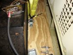
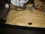
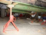
DSC05502.jpgDSC05504.jpgDSC05505.jpgDSC05506.jpgDSC05507.jpg
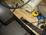
Pic number 1 shows the 5000 lb tie downs that go through the plywood and through the frame side rail which is 2X3 angle about 1/8" thick.

Pic No 2 shows 1/2" eyebolt that goes through the plywood, and through tapped hole in the frame and locknut installed below. To the left of the eyebolt is a 3/8X 1 1/2" grade 8 bolt which also goes through a tapped hole and locknut on bottom side. I have another dozen or so of those bolts while will be added when time permits and is going to take lots of precise measurement as I want them to go through the 4" C channel cross members. 3/4" treated plywood tends to come in a slightly warped condition and doesn't flatten out till you explain to it where it is wanted and you bolt it down and or add a lot of weight to it and I have done both.

The eyebolts installed here have another use which is to secure fuel cans and I think I can carry about five of them secured by ratchet strap and secured by lock & chain.


Pic No 3 shows underside of trailer and axle. Did not get good detail on the way the springs are attached to the chassis and will try and do that next time. It is up on jack stands to allow me access to underside on creeper.

Pic No 4 gives details of first wiring with 3 feet of 10/4. On the outside is going to be a twist lock 4 prong plug that my other extensions will plug into. This plug in will also double as connector to a weather proof box on the floor with outlets into four plug boxes, one on each hot leg and on the end of that run perhaps a 3 prong stove receptacle. It was interesting as I figured out right quick the plastic wrench was time consuming so I got out a 1 3/8" 1/2" drive socket which fit the nuts on L2, L3, L0 and Ground with no problem but did not want to go on L1. I pulled it off and it was oversize so I reduced the diameter a bit at a time until the socket would go on and allow for easier snugging down.

Pic No 5 shows the ramp the PO used to drive the big bikes up. The frame is nice and stiff but not heavy as it has to be strong enough to routinely handle Honda Gold Wings which are 900 lb range with rider so figure it has had a long line of 1100 lb applications without warping. As previous pic shows the ramp in the up position leans to the rear about at about a 40° degree angle. I like this as it advises followers that they are following something that is different and by the time I get through with the reflective tape their attention is assured and I may even hook up clearance lights on the D ring handles on the sides. I also have some green reflective sign panels like are used on mail boxes for 911 address identification that I might attach via light chain so they will have constant movement while on the road and will be a good attention getter at night. The MEP will also be "accessorized" haha.

DSC05503.jpg
This pic shows the first 10/4 SOOW cord coming out and is three feet long. Also it will be noticed the rear bolts in the sled have not been installed as yet. I put in the fronts, the tie downs then added the hold down strap and will do the rear holes with 3/4" No 8 bolts next.
The square piece of steel under the ramp is the pivot point for my 3" pry bar I used to move generator into position and measing both sides to center it. Pic also shows strap stock that is used to hold the ramp in place. !/2" eye bolt and regular bolt are inserted through plywood and into tapped holes and lock nuts on the underside. The PO had a good idea of how to secure the ramp from coming loose I will photograph later so others can see. The fenders on the trailer are very substantial and can be used as "STEP" location.
 
Last edited:

Chainbreaker

Well-known member
1,750
1,845
113
Location
Oregon
That's a nice size trailer for your genset. BTW, I thought I was the only one who saved sardine tins to put odds-n-ends in...lol.

Not sure exactly how you delete duplicate photo's never had to do that here. If you go in to edit mode can you select each one and just hit delete, or right click and hit delete?
 

Humpy

New member
62
1
0
Location
Springfield, South Carolina
Exactly what I tried, went to edit, highlighted, right click and no DELETE option.

I save tuna and sardine cans and wife can't stand it. I used them to mix Marinetex and Devcon 2 Ton Epoxy as well in them too.

Hopefully someone will come along and enlighten us on how to DELETE photos.

Yes trailer seems to be perfect size to pull behind passenger cars, even smaller ones. It was rather hard to see in side mirrors backing but with the generator on board , it stands up nice to let me know where the trailer is backing.

It has 12" wheels now and I think they will be OK.

Hit the mother load yesterday. Friend had 25 feet of 10/4 SOOW new he never uncoiled and I traded him two gallons of wheel weights for it. I asked him if by chance he had any 12/3 wire so as we looked for it he pointed out a pile of well pump wire whichs appears to be 10/3 and it is stranded and he gave it to me. Looks to be 108 feet. That should allow me to power up house and shop at same time I think.
 
Last edited:

Chainbreaker

Well-known member
1,750
1,845
113
Location
Oregon
What happens if you place your cursor to right of photo and then hit backspace?

Also, not knowing your electrician skills, hopefully you have read the sticky "MEP-003 hook up question" and in particular Speddmon's post # 25 regarding grounding considerations, SDS vs Non SDS, etc. A confusing thread to read through but very informative:

http://www.steelsoldiers.com/showthread.php?40290-MEP-003A-hook-up-question

I use 6/4 SOOW from genset to a generator inlet box on house, I think with 10/4 your limited to under 50'. Since you only have 25' that shouldn't be a factor. Not sure how you intend to use the 108' of 12/3...
 
Last edited:

Humpy

New member
62
1
0
Location
Springfield, South Carolina
Chainbreaker, thanks so much for the tip about using the backspace to dump pics. Would have never thought of that.

Read the sticky and no 25 as you suggested thus begging the question this is a MEP802 and the grounding is addressed by a ground terminal in the box as well as the neutral which makes for a rugged and simple hook up for additional grounding or primary grounding as needed.

On the 10/4 I ran red to L1, black to L3, White to L0 and Green to ground and I am favoring never pass up a good ground and my intention was to take a piece of solid copper service wire (non insulated) as was used on residential service connections in the last century and taking my backhoe and digging into wet ground (our washing machine drain goes into the yard) and bury one end about six feet down where it will be wet till the end of the world and the other end to the generator ground when set up for long term running. I got about 75' sections of it from a old house that burned 25+ years ago and the power guys arrived, cut the wire from house and at the pole and left it laying for whoever wanted it.


To those of you that were not on the Drop Zone in the first half of the last century at one time copper wire was considered to be trash ! ! ! ! ! And being the local president of Dumpster Divers of America Local 357-45-7.62-30-06-300M and a life member of the NRA (Never Refuse Anything) Chapter I saved it from going to the land fill.

I arrived at the desire to establish multliple grounding based on a conversation I had with local power linemen 27+ years ago when I was visiting my (to be wife) and staying at her folks house I was getting electrical flow from the shower. Her father did not believe it but she did as she said she had experienced it as well so next trip up I brought my multimeter and was getting 6 volts from the shower. I looked at ground on service panel and everything looked good so the power guys were called and upon arrival they never came to house but stopped at the pole and connected their big trillion volt unit and it even read a trickle as well.

They explained in that area the grounding ability of the soil was poor and they had problems all over that area with such and they suggested/hoped if we could run a ground wire from the house panel to the well casing (in those days they were steel) and secure it well that it would help folks in the whole area. Also knew a another Amateur Radio type and he was over commo for the railroad and he said at one relay sight he had to sink a ground rod 80' down to get a decent ground for their transmitter. Thusly I arrived at the conclusion of a additional grounding would not hurt.

In the last ice storm here I ran a Honda EZ3500 into house after switching off main panel breakers and that kept the fridge/freezer/TV/computer and motor on gas furnace going.

Be assured I have linemen friends who have seen my set up and they have no problem with it with the associated "AS LONG AS YOU TURN OFF MAIN BREAKERS" caution and I assured them in a power failure I call it in, then go kill the breakers, then go get the generator and before final plug in go back and make double sure the mains are Off. When I see outside yard light come on my shop I know power is back at which point I turn off Gen, unplug from generator and the house, roll it up and go back in and restore main breakers.

When my shop was built I had separate service run in for it and the well pump (that flows 45 gpm) is hooked to the shop service thusly if I get a residential fire I can kill breakers in the house and start water flow while the rest of my guys get the pumper and tankers rolling from the station and mutual aide pumpers/tankers as well for when they arrive I will have bunkered up and just waiting for the first in unit to grab a air pack and the nozzle.(Fire/Rescue Member last 20+)

The 10/3 wire is on hold. I am also CEO of WBH (We Be Hoarders) When we get ice storms we pre-position drinking water and fill the tub with flush water and we are good to go for about a week. (Gas furnace/gas radient wall heater) In a longer term outage I am thinking I could kill main breakers in shop and wire it so the well pump (1.5HP) would come on. I have a separate 5 KW I could use for that and wife will be able to shower. As for me our main station has a 22KW unit permanently wired into our HQ station and shower there. I was thinking I could run an additional SJOW to the shop panel from the 802 and run it from the gen. Will have to see what the load is when I get the 802 hooked up for a trial run.

A squirrel shorted a line about six weeks ago, I called it in, went and got my newer Powerback 5250 out, plugged it into house and ran it about 75 minutes till the power came back.

At any rate that is my thought rationale/experience on additional grounding.

I just moved a power pole w/ light the power guys took down when pole failed inspection and they left it for me so I dug a 4' hole and reset the pole (cut off deterriorated section and remounted yard light) behind my shop and I reconnected the wiring to my shop service and reinstalled the pole ground to the housing on the light. I also have it wired to a light switch in the shop so I can disable that light as desired. Basically in a power failure I could kill everything in my shop except the power to the well pump and leave on three 8W LED bulbs that are on 24/365.

I had them put in a 400W flood on another pole which was less than installing another 100W yard light and now I have 400W cheaper than two 100W that is aimable light source rather than a "to whom it may concern" lighting plan.

Again Sir, thanks so much for the inputs/suggestions. I had not looked into 003 wiring as I did not want to announce to folks a mile away I had power. I would appreciate your opinion on multiple grounds as well. DE AC4HT
 
Last edited:

Chainbreaker

Well-known member
1,750
1,845
113
Location
Oregon
Glad the backspace photo delete tip worked!

Be assured I have linemen friends who have seen my set up and they have no problem with it with the associated "AS LONG AS YOU TURN OFF MAIN BREAKERS" caution and I assured them in a power failure I call it in, then go kill the breakers, then go get the generator and before final plug in go back and make double sure the mains are Off. When I see outside yard light come on my shop I know power is back at which point I turn off Gen, unplug from generator and the house, roll it up and go back in and restore main breakers.
I would STRONGLY recommend installing a Generator Interlock Kit as a minimum in your panel if you have the room for one or an appropriate transfer switch. Hooking it up without one is against code and a liability, as well as possibly invalidating your H.O. Insurance in the event something went wrong. During a power outage/storm and darkness its just too easy to get out of synch as to whether you left the Main Breakers On or Off. With an Interlock Kit there is NEVER any question about safety and even your wife can work it then if needed.

See my post #72 in this thread to see the interlock kit I used; it cost $69 (I have 2 interlock kits installed, one at house and one at barn/shop service entrances):

http://www.steelsoldiers.com/showthread.php?64672-Mep-003&p=1453639&highlight=#post1453639

Edit: After rereading your post #15 it doesn't sound like your particular house has any known grounding issues. It sounds as if your thinking, based on other somewhat iffy grounding experiences in your locality, is that more grounding is better. If you are talking about just extending your house utility ground in series (running copper wire out to damp location grounding point) to assure consistent grounding in your soil conditions that might be OK. If you are thinking dual grounds (house utility gnd AND Generator gnd) when using generator for backup purposes (NON Self Derived System) there is controversy over that practice. As I read it, there is concern about setting up path for gnd loop potential. There are several comments discussing that scenario in the Hooking Up link I posted earlier.
 
Last edited:
Top