• Steel Soldiers now has a few new forums, read more about it at: New Munitions Forums!

  • Microsoft MSN, Live, Hotmail, Outlook email users may not be receiving emails. We are working to resolve this issue. Please add support@steelsoldiers.com to your trusted contacts.

surplus center distribution panel project

Jimc

Member
725
1
18
Location
Mullica, nj
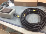
quite awhile back i picked up two of those distribution panels that surplus center has for sale at about $8ea. i have been wanting to do something with at least one of them so i finally ordered up a few parts so i can put one to use if i ever have the need. i see some guys mount them to the generator but i decided to put mine on a 50ft piece of milspec 10/4 SO cord that i grabbed on the big auction site. this way if i was to ever use the 002 or 003 on say a jobsite or to power some tools then it can sit a distance away and you can still plug in. so here is what i did.....

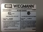
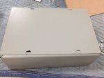
first i picked up this nice plain metal hubble box. it measures 12 x 8 x 4. ran me about $29 shipped. the part # is in the one pic.
IMG_1583.JPGIMG_1586.JPG

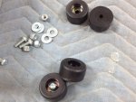
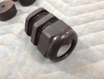
i ordered a waterproof cord grip and some rubber feet from mcmaster carr. the cord grip is pt# 69915k72 and the rubber feet were pt# 9540k28. if anyone decides to do this in the future keep in mind the cord grip size may vary depending on the diameter of the cable you are using. you may need to choose one of a different size.
IMG_1585.JPGIMG_1582.jpg

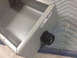
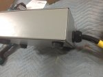
i took a hole saw and drilled a hole to accept the cord grip. holes were already in the bottom of the box for the feet. originally meant to mount to a wall im sure. with the feet bolted in place and cord grip tightened i slipped about 12" of the cord through the grip and tightened it down.
IMG_1591.JPGIMG_1595.JPG

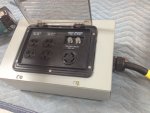
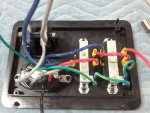
now i opened up the surplus center panel, cut the wires going to the connection block and took the plastic back off. there is a plastic pin on each corner of the mounting flange. i clipped them off and sanded them smooth to remove them 100%. now i took the flat cover panel for the hubble box and cut a square hole in it so the panel would drop in place. around the plastic panel flange i drilled and countersunk 6 small holes to accept some #6x1/2" ss sheetmetal screws. i applied some black urethane sealant around the flange, put it in place on the metal panel and screwed it together. you can use silicone if you want. the urethane stuff is a harder rubber and way higher strength bond. basically the same stuff they set your windshield in your car with. once all that was done i wired the panel up to the cord. the color code for the panel is: blue and grey are hot legs, red and black neutral and the yellow with green tracer is ground.
IMG_1590.jpgIMG_1594.JPGIMG_1593.JPG

there you have it! a good way to spend 15 times more money than you spent on the original panel itself lol. actually all together including the cord and the panel i might have $170 in the whole deal. the cable is the real expensive part. wire aint cheap anymore.
 

Jimc

Member
725
1
18
Location
Mullica, nj
Yeah john, thats all the manufacturers wiring. They did have the neutral and ground bonded together. Not no more though. I took care of all that. As for the box, that is grounded. It came with a ground screw so i ran a ground wire to it.....thanks
 

95blklsc

Member
39
0
6
Location
MA
What is the part number for that panel? I may set up something like this to have in case I need to do something other than power my house.
 

tobyS

Well-known member
4,832
833
113
Location
IN
Actually John and JimC the jumper is connecting the hot side to the ground, not the neutral. That would be a direct short circuit, not simply a bonded neutral. The black is power and the white neutral, so that ground wire at the end, going to the terminal where the red wire is connected... should not be there. I hope that is the one you removed Jim.

OOPS...that is set up for 240v and two 120 circuits, making the blue also a hot line, therefor there is not a neutral at the (right side in photo) 115 volt outlet. There should be a white wire to the silver terminal of each 115 volt receptacle, in addition to removing that ground. Thus one circuit is black wire and one is blue wire. Across black (red) and blue should measure 240v.
 
Last edited:

Jimc

Member
725
1
18
Location
Mullica, nj
toby, this is the wiring direct from the manufacturer and the wire colors on this panel didnt conform to any standard. the black wire that changes to red is actually the neural so the neutral and ground were bonded. fortunately for me and the thousands of others that bought this, that wasnt a direct short. the hot legs are actually the blue and grey wires
 

tobyS

Well-known member
4,832
833
113
Location
IN
Ok...but NEC is different (grey looks white in photo). My personal preference is to make the change at the earliest place possible (which would be the recept on the gen.), but you must have followed it out. Bonded and licensed, I don't go against NEC knowingly.
 

Triple Jim

Well-known member
1,376
291
83
Location
North Carolina
If I had one of those, I'd rewire the whole thing to meet US standards. I don't want to open up a box like that a year or two from now and be confused about what color means what. I'm confused enough already, without help like that. :-D
 

steelypip

Active member
769
68
28
Location
Charlottesville, VA
I've got one of those. Nice to see somebody putting it to work. Mine's going on the end of a big piece of 8/4 SO to become a contractor box for building my new shed.
 

tobyS

Well-known member
4,832
833
113
Location
IN
I'd change the color code to black and blue for the power leads, white for neutral and leave the green alone. That will require white colored electrical tape and regular black. Tape the neutral (red and black) wires white and tape the gray wire black. Connect blue and (new) black to the hot leads in your so, white to white for neutral and green to green. Remove the green jumper bonding from ground to neutral (or don't...shouldn't matter... except with GFI it may need to be removed).
 

johnray13

Member
121
0
16
Location
Chantilly, Va
Since the neutral can carry voltage, you don;t want them bonded anywhere except the first point of service, in this case the generator. Otherwise you will create a condition in which your ground conductor could carry transient voltage and under the right circumstances, a number of bad things can happen.

John
 

ctfjr

Member
83
2
8
Location
central CT
Since the neutral can carry voltage, you don;t want them bonded anywhere except the first point of service, in this case the generator. Otherwise you will create a condition in which your ground conductor could carry transient voltage and under the right circumstances, a number of bad things can happen.

John
John I am confused by your statement, perhaps you can help this old fart understand it :) I can see where there would be some current flow through the neutral but if the neutral is grounded where is the 'voltage' measured from? I get that there is some I*R drop in the wire but I would imagine that would be pretty small. . .
 

quickfarms

Well-known member
3,495
25
48
Location
Orange Junction, CA
This panel was designed to have the power supplied through the plug on the back of the unit. Over the years I have seen a lot of wiring that does not confirm to normal American AC wiring colors. The military for example uses all white wires on a lot of equipment such as generators.

The issues of the neutral and ground being bonded is not a concern if you remember that this panel was originally designed to be mounted on the generator.

We are using this for a purpose that it was not designed for.

If you are concerned than you should just buy a commercial spider box.

You should always wire a device by function and not blindly follow the wire colors.
 

tobyS

Well-known member
4,832
833
113
Location
IN
ctfjr, I think John may be referring to a circuit that instead of using the neutral for carrying current, it passes through the ground for some reason. Sometimes, that can be a source for a bad connection that then heats up. He can expand, but in the scheme of things, would probably never be an issue. And in good GFI circuits, the neutral is monitored separately from ground and tie-ing them together will prevent it from seeing a fault to ground on the circuit beyond the GFI.

I have proposed only re-taping them (white and black electrical tape) to make them sensible to an electrician and an electrical inspector, should your job-site encounter one. Everyone has black e-tape and if need be, rob the white from a first aid cabinet. Simple and up to code...not even another twisty involved. EDIT---also disconnect the bonding to ground at the recep and it will be fully to NEC.
 
Last edited:

johnray13

Member
121
0
16
Location
Chantilly, Va
John I am confused by your statement, perhaps you can help this old fart understand it :) I can see where there would be some current flow through the neutral but if the neutral is grounded where is the 'voltage' measured from? I get that there is some I*R drop in the wire but I would imagine that would be pretty small. . .
In simplest terms, the NEC prohibits the ground wire from being used as a current carrying conductor. When it is bonded to the neutral at the receptacle, it becomes one (in parallel) with the neutral, carrying current back to the generator.

John
 
224
1
16
Location
Independence, OH
As johnray13 says, the neutral IS the power return wire. The ground wire IS a safety device. It doesn't matter that they connect to the same ground at the breaker box. In a house, this is the closest you can get without providing a separate Earth ground for the two wires. If the ground wire starts carrying current there IS a problem. It's all about safety. For example, the way a GFI works is there is a transformer that monitors the current flow through the neutral wire and the power wire. As long as the current going through the two lines balance each other out nothing happens. If the current flow is unequal, there is an issue. The power may be shorting to ground through water like a wet power tool or is already surging through some hapless victim, the breaker will trip cutting power to the outlet.
 
Top
AdBlock Detected

We get it, advertisements are annoying!

Sure, ad-blocking software does a great job at blocking ads, but it also blocks useful features of our website like our supporting vendors. Their ads help keep Steel Soldiers going. Please consider disabling your ad blockers for the site. Thanks!

I've Disabled AdBlock
No Thanks