BadBrad1
New member
- 23
- 0
- 0
- Location
- KOKOMO, INDIANA
OK my $349.00 GSA MEP-002A is up and running and making power but I had some issues (and still have a few).
Problem 1: Fuel system gunk and corrosion, took off all lines, filters, and tank, cleaned an new filters.
Problem 2: Fuel tank had 2 pinhole leaks, filled with water and MIG welded up the holes...yeah that was fun.
Problem 3: Motor would try to start but when switched over to prime/run position it would stop. Turns out the fuel pump cutoff solenoid was dropping cutting off the fuel, shutting down engine as soon as it was switched over to prime/run position. Pulled fuel cutoff solenoid and did a test run and it ran fine, I traced the problem to the oil pressure switch not closing, thus not allowing K1 holding circuit to complete when start switch was moved to run. Oil pressure on gauge was solid 25 lbs So I jumped out the oil pressure switch for test purposes, installed the cutoff solenoid and it fired up and ran and stopped when switch to STOP...all seemed good.
Problem 4: No 24VDC charging. So I checked the fuse on the 24VDC regulator, it was blown. Removed the blower cover looked at the wiring and it didn't make sense....somebody had been there before... and miss-wired the regulator. Instead of having the white wires going to T1 and T2 (connecting to the two stator leads on the terminal strip) the wire that should have been on T-1 was one slot to the left tied to GROUND. Rewired that and fired it up...meter in the green charging at 1.8 AMPS measured at the fuse with amp-meter all is well...well kind of.
NOW it gets interesting...went to start it next day...spins over but no start...not even a puff...WTF...
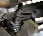
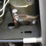
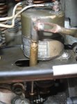
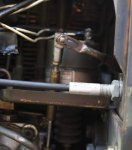
 ...Check out the injector pump linkage and it is binding....just a little.. the linkage (brass dog bone looking part with the ball joints) is dragging on the side of the Fuel cutoff solenoid not allowing the throttle to open all the way. Seems the lever coming over from the speed governor had been bent at some point messing up the linkage geometry and letting it bind up.
So I re-contour the Lever coming off the governor so the brass part was clear of the solenoid and free from contact with frame. Doing this necessitated readjusting the length of the aforementioned "dog bone" linkage so full throttle could be obtained.
Buckled it up and hit the start switch and away she went . ..adjusted for 61.5 Hz using my meter in the convenience outlet (panel gauge is 2.5 HZ off). I adjust the voltage to 120v. voltage adjusts fine.
Check out all the RECONNECTION switch positions, 120 single phase, 240 single phase and 120/208 3 phase, all voltages measure good across all phases at output lugs.
LOAD TEST TIME: All I had handy was a 1200 watt heat gun (10 amp load) so I plug it in the convenience outlet and turned it on. It worked fine but there was about a 4 HZ droop instead of the expected 1.5 HZ droop .
 . I could see the governor linkage move adding throttle with load but it did not add enough. Using the fine tune knob I could adjust it up to spec. but then when load was removed it was running fast, the governor should be correcting better then it is IMHO.
So as it sits:
I need a new oil pressure switch--- Anybody know a source for these? Seems it is 24VDC rated, 14 PSI normally open pressure switch.
Looks like I need to go through the speed control governor setup, it looks like a brand new throttle cable was just put on the thing so between it and the bunged up linkage this should be fun.
Any advice/tips/tricks or shortcuts on doing the governor setup ??
It's been interesting....
Problem 1: Fuel system gunk and corrosion, took off all lines, filters, and tank, cleaned an new filters.
Problem 2: Fuel tank had 2 pinhole leaks, filled with water and MIG welded up the holes...yeah that was fun.
Problem 3: Motor would try to start but when switched over to prime/run position it would stop. Turns out the fuel pump cutoff solenoid was dropping cutting off the fuel, shutting down engine as soon as it was switched over to prime/run position. Pulled fuel cutoff solenoid and did a test run and it ran fine, I traced the problem to the oil pressure switch not closing, thus not allowing K1 holding circuit to complete when start switch was moved to run. Oil pressure on gauge was solid 25 lbs So I jumped out the oil pressure switch for test purposes, installed the cutoff solenoid and it fired up and ran and stopped when switch to STOP...all seemed good.
Problem 4: No 24VDC charging. So I checked the fuse on the 24VDC regulator, it was blown. Removed the blower cover looked at the wiring and it didn't make sense....somebody had been there before... and miss-wired the regulator. Instead of having the white wires going to T1 and T2 (connecting to the two stator leads on the terminal strip) the wire that should have been on T-1 was one slot to the left tied to GROUND. Rewired that and fired it up...meter in the green charging at 1.8 AMPS measured at the fuse with amp-meter all is well...well kind of.
NOW it gets interesting...went to start it next day...spins over but no start...not even a puff...WTF...
So I re-contour the Lever coming off the governor so the brass part was clear of the solenoid and free from contact with frame. Doing this necessitated readjusting the length of the aforementioned "dog bone" linkage so full throttle could be obtained.
Buckled it up and hit the start switch and away she went .
Check out all the RECONNECTION switch positions, 120 single phase, 240 single phase and 120/208 3 phase, all voltages measure good across all phases at output lugs.
LOAD TEST TIME: All I had handy was a 1200 watt heat gun (10 amp load) so I plug it in the convenience outlet and turned it on. It worked fine but there was about a 4 HZ droop instead of the expected 1.5 HZ droop .
So as it sits:
I need a new oil pressure switch--- Anybody know a source for these? Seems it is 24VDC rated, 14 PSI normally open pressure switch.
Looks like I need to go through the speed control governor setup, it looks like a brand new throttle cable was just put on the thing so between it and the bunged up linkage this should be fun.
Any advice/tips/tricks or shortcuts on doing the governor setup ??
It's been interesting....
Last edited:


