• Steel Soldiers now has a few new forums, read more about it at: New Munitions Forums!

  • Microsoft MSN, Live, Hotmail, Outlook email users may not be receiving emails. We are working to resolve this issue. Please add support@steelsoldiers.com to your trusted contacts.

Tacho install success. Maybe some good info's

drewzee87t

Member
70
8
8
Location
MO ozarks
I have been through a couple different ringers on trying to get a tach on my 1028. I finally got the recipe correct today.

after a couple of interesting attempts, I did get a VDO 333-156 (which I believe someone here has previously recommended). It's a 52mm 4k alternator signal gauge.

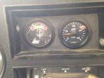
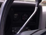
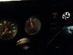
I have included some pics, it works great and the install was pretty clean. I bench installed it in the engine bay and set it up and calibrated it, then installed it to the bezel and wired it inside.

Once I had it bench calibrated, I used a 2" hole saw to cut out the hole, then widened it to fit with a half round. I switched the volt meter to the new hole as I like the visibility on the tach to where the volt gauge was.

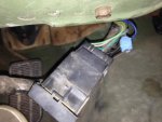
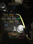
The tacho pulse from the alt runs to the STE system, I was able to find it under the dash and the wire to tap is in the photos below. Otherwise, I just tapped the light bulb and ground from the volt meter and for the main gauge power I tapped into the fuse at the horn and put in a inline fuse. Everything worked perfect. I hope this helps some people, its a great gauge and looks good, very easy. I have a good source for these at way less than Jegs or Summit, pm me for info. I am not in any way associated with this business, but the gauge was less than $100 shipped.

Questions or critical comments welcome.
IMG_1202.jpgIMG_1191.jpgIMG_1190.jpgIMG_1197.jpgIMG_1192.jpg
Thanks
 

richingalveston

Well-known member
1,715
120
63
Location
galveston/Texas
looks great, only critical item I see is that you tapped into the horn circuit. From what I have heard there are a lot of problems with that circuit already because it feeds a couple other items also. You may be asking for trouble putting more load on that circuit
It may not be an issue but I thought I would bring it to your attention.

Nice work.
 

PJL

Member
140
6
18
Location
Way south of Seattle, WA
That looks very nice. Like a factory install. I agree on the use of horn power. I believe it's always hot and is switched off by the blackout switch. But if it works and you're happy...
 

drewzee87t

Member
70
8
8
Location
MO ozarks
Thanks guys. To clarify, I tapped in "next to" the horn circuit. It's a single spade with a switched supply (only hot when key on). I am pretty sure the horn circuit fuse is jumpered to the headlight fuse, which is a troublesome circuit, but that's always hot.
 

MarcusOReallyus

Well-known member
4,524
816
113
Location
Virginia
Looks good! :beer:

I love the way you cheated on the tach sense. :mrgreen:


A word of advice: when using taps, stick with the kind that have a double connector. They are light years more reliable. Slop some dielectric grease in there, use some pliers that have parallel jaws (or as close as you can get them), and you'll have a solid connection that will stay that way for many years.


electrical taps bad and good.jpg
 

drewzee87t

Member
70
8
8
Location
MO ozarks
For the pulse I tapped into the single brown wire coming from the driver's side alternator.
Hi goldneagle. The brown wire W output of the DS alternator terminates inside the truck in the STE system next to the big round STE connector. I just avoided any wire runs from the engine compartment by getting it under the dash....

AND...thank you very much, your restoration post was what got me going this direction as I really didn't care for the tinytach solution.
 
Last edited:

Tinstar

Super Moderator
Super Moderator
Steel Soldiers Supporter
4,292
1,779
113
Location
Edmond, Oklahoma
Hi goldneagle. The brown wire W output of the DS alternator terminates inside the truck in the STE system next to the big round STE connector. I just avoided any wire runs from the engine compartment by getting it under the dash....

AND...thank you very much, your restoration post was what got me going this direction as I really didn't care for the tinytach solution.
So this tach reads the DS pulse signal directly?
Nothing fancy to do? Just hook up and calibrate?
 

drewzee87t

Member
70
8
8
Location
MO ozarks
Bench install and calibrate:

I took three wires, each about three feet long and installed a crimp ¼ female spade connector to one side of each. The other end of each wire strip some insulation off about ¾”.

Hook up the spades to the gauge +, - and signal connectors.

Start and warm up truck until it is running on low idle (warm)

Remove the boot at the driver side alternator that connects to the W (alt signal) port (brown wire). It is just a pin that sticks out. Wrap the stripped end of the wire connected to the signal port on the gauge around this pin a couple times and put the brown wire/boot back on to hold it in place. You will note that this provides a 7.3 to 7.5 volt output when running.

Connect the plus wire and ground wire to the front battery positive and any suitable ground (be careful not to get any wiring caught up in fans, belts etc.)
Guage will read. In my case the gauge read full tilt 4k RPM. Using a jeweler screwdriver, set the dip switches until the needle gets into a range. If your truck is normally tuned, you are shooting for 650 RPM + or – 25 (Per TM 20). I think I settled on dip switch setting of OFF, OFF, ON which settled at about 600.
On the side of the gauge (or back if you have a different VDO gauge) there is a calibration screw, adjust that until you are at 650 RPM on the gauge.

That’s it for calibration. One lesson learned, I set the RPM on the gauge staring directly at it. In reality you will be looking DOWN at the gauge, you may want to adjust for parallax in your viewing angle as mine installed appears to be maybe 625 when viewed from the driver seat. I am not very tall either. The gauge is in 200 RPM increments so you aren’t going to ever get a perfect calibration.

Carefully remove the wire connections from battery, ground and alternator and install your gauge in the truck.

Install:

The gauge just requires switched plus (hot when key on) 12v (make sure it’s 12, not 24), ground and the lightbulb requires +12v that is controlled by headlight switch and ground, and the signal from the alternator.

You can tap into the ground wire on the volt-meter to supply all the grounds. You can't use the voltmeter + because it is 24v

You can tap into the light bulb on the voltmeter to supply the positive for the light bulb.

I used the empty single spade slot next to the horn fuse (switched 12v) and put an inline fuse (10 amp, but 5 would be more than enough) for the main gauge power

The alternator signal wire can be accessed in the truck as shown in the photo. It terminates at the tach adaptor circuit board which is part of the STE/ICE wiring harness (the big round metal plug with the screw top). See the picture. You can test to make sure you have the right wire by reading same 7.3-7.5 volts that you got at the alternator in the engine bay.

Use the wires you already made as part of the bench test to complete the install - you will have plenty of length and can trim as you complete.

Hope this helps.
 
Last edited:

Craig C

New member
106
1
0
Location
San Jose, CA
I wonder how much of this info can be used to install a tach in a HMMWV using the STE/ICE wiring as well. Of course it would require a 24v tach or some dropping
resistors to produce 12 v.
 
Last edited:

Ilikemtb999

Active member
701
45
28
Location
Denver, CO
I have this gauge and it goes dead over 2k and then as soon as the rpm is under 2k it reads again. I'm at a loss but I'm going to compare to your dip switch settings.
 

drewzee87t

Member
70
8
8
Location
MO ozarks
I would think your switch settings are in the incorrect range. Check it and please get back to us. Thank you for your interest in this thread. Post up your results using the bench test I provided. I think it works awesome and am very happy with it.
 

Ilikemtb999

Active member
701
45
28
Location
Denver, CO
I would think your switch settings are in the incorrect range. Check it and please get back to us. Thank you for your interest in this thread. Post up your results using the bench test I provided. I think it works awesome and am very happy with it.

I adjusted my switches to your settings per this thread and my tach no longer moves. I had mine set at OFF ON OFF

I think I'll try putting it back to my setting and then trying to use the adjustment screw.
 

Tinstar

Super Moderator
Super Moderator
Steel Soldiers Supporter
4,292
1,779
113
Location
Edmond, Oklahoma
What switch settings finally worked?
I know OP said off off on, but with others that didn't work.

Installing mine this weekend
 

Tinstar

Super Moderator
Super Moderator
Steel Soldiers Supporter
4,292
1,779
113
Location
Edmond, Oklahoma
Disregard

Just did rough hookup

These settings worked for me [full range]
1) Down
2) Down
3) Up
Very minor tuning and now spot on.
Just like OP said.

Already knew idle rpm from laser reader.
 

richingalveston

Well-known member
1,715
120
63
Location
galveston/Texas
What lazer reader are you using? Can you give me some info on that device? I need something to calibrate my Dakota digital module. I think it is close but I have no way to verify. I am considering buying a tiny tach just to use for calibration and keep on the shelf.

Thanks
Rich
 
Top
AdBlock Detected

We get it, advertisements are annoying!

Sure, ad-blocking software does a great job at blocking ads, but it also blocks useful features of our website like our supporting vendors. Their ads help keep Steel Soldiers going. Please consider disabling your ad blockers for the site. Thanks!

I've Disabled AdBlock
No Thanks