• Steel Soldiers now has a few new forums, read more about it at: New Munitions Forums!

  • Microsoft MSN, Live, Hotmail, Outlook email users may not be receiving emails. We are working to resolve this issue. Please add support@steelsoldiers.com to your trusted contacts.

Tachometer Wire Connector

mgFray

Well-known member
Steel Soldiers Supporter
713
987
93
Location
Southern Minnesota
I'm considering adding a tach to my HMMWV, but don't want to cut any of the existing wiring (or use taps).

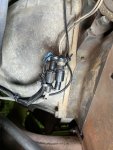
Looking at the pulse tach on the back of the engine, I should be able to just move it to my own wiring _IF_ I can find the right connectors.

tach-connector.jpg

Does anyone happen to know what the male/female connectors are for the mechanical tach and where to get single quantities?
 

mgFray

Well-known member
Steel Soldiers Supporter
713
987
93
Location
Southern Minnesota
Love it when I can just reply to myself. Found it in TM 9-2320-280-24P-1 - Figure 76. It's "View A - part 2".. 5935011495165 - 7N9738 and apparently it's a pretty common connector!

Now to pickup both a male and female version and verify it fits.. then I can build a harness for a tach.

Edit: 7N9738 is only one of the two connectors, the other side is 7N7782. See figure 86 (A2 harness), items 26 and 27, this is apparently the mating pair.
 
Last edited:

TOBASH

Father, Surgeon, Cantankerous Grouch
Steel Soldiers Supporter
Supporting Vendor
3,596
3,518
113
Location
Brooklyn, NY
Cut the wires, insert packard three ways, and then use packard connectors to attach wires that lead to the tachometer.
 

springer1981

Well-known member
844
1,150
93
Location
Maine
I'm considering adding a tach to my HMMWV, but don't want to cut any of the existing wiring (or use taps).

Looking at the pulse tach on the back of the engine, I should be able to just move it to my own wiring _IF_ I can find the right connectors.

View attachment 876197

Does anyone happen to know what the male/female connectors are for the mechanical tach and where to get single quantities?
You should use a twisted pair for the wiring. I have some of those connectors, pins, wire and the crimper to do the job if you don't get anywhere.
 

Retiredwarhorses

Well-known member
Steel Soldiers Supporter
4,414
4,207
113
Location
Brentwood, Calif
I'm considering adding a tach to my HMMWV, but don't want to cut any of the existing wiring (or use taps).

Looking at the pulse tach on the back of the engine, I should be able to just move it to my own wiring _IF_ I can find the right connectors.

View attachment 876197

Does anyone happen to know what the male/female connectors are for the mechanical tach and where to get single quantities?
Just use posi-tap connector, simple and no Splicing
 

mgFray

Well-known member
Steel Soldiers Supporter
713
987
93
Location
Southern Minnesota
Just use posi-tap connector, simple and no Splicing
(on non HMMWV) I've seen problems with both posi-tap and those cheap-o blue tap connectors. Both rust due to water inflitration into the tap itself, or damage to the wire so that over time it's current carrying is reduced and the wire breaks due to heat (or may vibration or both). So I'd rather just use the connectors that are already there and "intercept" it in my own wiring harness.

If posi-taps work for you, great. I know a lot of people use them, I'm just of the opinion I don't want to splice (or tap) the wires unless I have to.
 

Retiredwarhorses

Well-known member
Steel Soldiers Supporter
4,414
4,207
113
Location
Brentwood, Calif
.
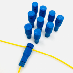
Posi-Tap connectors are much more durable than scotch-locks too!

View attachment 876230
they are used in the installation of the red dot kits to connect powe
(on non HMMWV) I've seen problems with both posi-tap and those cheap-o blue tap connectors. Both rust due to water inflitration into the tap itself, or damage to the wire so that over time it's current carrying is reduced and the wire breaks due to heat (or may vibration or both). So I'd rather just use the connectors that are already there and "intercept" it in my own wiring harness.

If posi-taps work for you, great. I know a lot of people use them, I'm just of the opinion I don't want to splice (or tap) the wires unless I have to.

I’ve never seen one fail, the red dot AC uses them to connect power off the heater switch…unless your truck is underwater I doubt your going to have a problem with this so called “rust”.
but hey…to,each his own.
 

mgFray

Well-known member
Steel Soldiers Supporter
713
987
93
Location
Southern Minnesota
My bad experiences with taps is mostly from 80's cars in the 90's. Maybe wiring itself has improved or the taps have improved. (Like I said, the cheapo clip on ones are terrible.. posi-taps are _MUCH_ better, but I still ran into issues with them.

This was mostly when I was in high school either helping friends wire up lighting, radios or trailer harnesses on old rust buckets that were already beaten pretty badly.
 

mgFray

Well-known member
Steel Soldiers Supporter
713
987
93
Location
Southern Minnesota
Love it when I can just reply to myself. Found it in TM 9-2320-280-24P-1 - Figure 76. It's "View A - part 2".. 5935011495165 - 7N9738 and apparently it's a pretty common connector!

Now to pickup both a male and female version and verify it fits.. then I can build a harness for a tach.

Edit: 7N9738 is only one of the two connectors, the other side is 7N7782. See figure 86 (A2 harness), items 26 and 27, this is apparently the mating pair.
The number above (7N7782) is INCORRECT! Also if you order those from a cat dealer, you don't get any pins!

Instead, I found the numbers for the the connectors themselves -- can be ordered from Digikey/Mouser.. and I THINK the pins are correct. But I've not yet verified it:

Plug: ITT Cannon - SS2P - 120-8552-000
Receptacle: ITT Cannon - SS2R - 120-8551-000. (This is 7N9738!)

Individual Pin: 330-8672-000
Individual Socket: 031-8703-000

You need 1 Pin and 1 Socket PER CONNECTOR. I'm likely going to order the parts and verify everything above in the next week.

(I have also ordered myself a Tachometer, so I'm finally getting around to planning the wiring for this.)
 

mgFray

Well-known member
Steel Soldiers Supporter
713
987
93
Location
Southern Minnesota
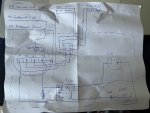
Ok, I have a plan. Anyone have any comments, I'm open to suggestions.

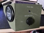
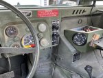
I ended up buying the box that mounts to the doghouse cover. I do NOT plan to drill through the cover, so I'll be adapting things a bit. The first thing I noticed, with the existing radio tray the tray is too close by about 1/2", not enough room.

So I plan to swap the radio tray floor mount bracket and move the tray forward about 1/2" - 1". Then at the top where it bolts to the dash, I'll use some spacers and longer bolts.

As for the tach box. I want to keep the STE/ICE TEST connector working, so I intend to install an ON-ON DPDT switch (similar to the real unit) so it can be switched. The real unit uses an MS24659-23G / Honeywell 2TL1-3G switch. Wow is that thing pricey. I'll likely go with a cheaper unit, but I might find a deal on ebay on a used switch.

Instead of the 12J1 port, I'm going to install a USB 83W A/C charger in there instead. The hole is the perfect size, and will be a nice clean place (under the radio tray) for a port. Out of the way visually, but functional.

Using a grommet in the back, or drilling a new hole for wiring in the side (we'll see) I should then be able to hook it up.

I've determined I need 9 - wires:

Engine area:
(2) 97A/97B _from_ the sensor to the "tach run" and STE/ICE TEST switch
(2) 97A/97B _to_ the body harness from the "tach run" and STE/ICE TEST switch

Cluster area:
(1) 27 - Instrument Power Feed
(1) 40 - Instrument Light Circuit
(1) 57 - Instrument Panel Ground

Battery are:
(1) +24V to feed the USB jack (through fuse and relay)
(1) GND (from the shunt) for the USB jack


Wiring this up:

Sensor 97A/97B -> center switch
bottom switch -> 97A/97B body harness
top switch -> tachometer +/- SIG

27 -> Tachometer (+)
40 -> Tachometer Light (+)
57 -> Tachometer (-) -> Tachometer Light (-)

24V relay:
57 -> 85 (relay ground)
27 -> 86 (relay trigger)
+24V -> Fuse -> 30 (relay power)
87 -> Switched +24V

USB Power:
Switched +24V -> (+)
GND -> (-)

I'm planning to put the fuse down in the battery compartment, everything else will be up in the Tach box.
 

mgFray

Well-known member
Steel Soldiers Supporter
713
987
93
Location
Southern Minnesota
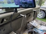
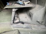
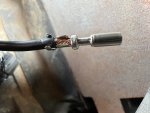
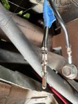
IMG_4785.jpegIMG_4786.jpegIMG_4787.jpeg

reversing the feet in the radio tray worked. A 2” metal spacer and 3 washers is pretty much perfect. Plenty of room for the tach.

I got the wiring run, and completed behind the dash and to the battery. Wire is run for the rpm sensor, but I’m waiting for the crimper and install tool before I hook that up.

With the wiring, the light on the tach will dim the same as the dash lights. It looks perfect.

Now to hook up the rpm sensor, get some velcro (hook and loop) to attach the tach to the doghouse cover, and to make a metal cover plate for the tach and it’s done.
 

mgFray

Well-known member
Steel Soldiers Supporter
713
987
93
Location
Southern Minnesota
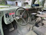
Figured I would add where I got the feeds from in the cluster.

Put in a Y to the oil pressure gauge for line 27 - Power Feed

Put in a Y on the dash light for line 40 - Dash Light Feed. Need to be careful pulling the wire since there is an inner plastic liner in the light connector that popped out of mine and had to be reinstalled.

Connected line 57 - Instrument ground to the ground screw on the cluster.
 
Top
AdBlock Detected

We get it, advertisements are annoying!

Sure, ad-blocking software does a great job at blocking ads, but it also blocks useful features of our website like our supporting vendors. Their ads help keep Steel Soldiers going. Please consider disabling your ad blockers for the site. Thanks!

I've Disabled AdBlock
No Thanks