
jakwi
Member
- 68
- 0
- 6
- Location
- Colorado Springs
I figured I'd share my latest project with you all.
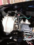
I decided to repurpose the driverside alternator since my cucv has been converted to 12v anyway it no longer served any purpose.
I've been reading about converting an alternator to a welder at the following site.
On-Board Welder
So this isn't my idea, but it seemed to me that the hard part was mounting an extra alternator. For us this was already done.
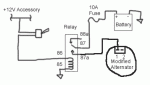
So I performed the modifications to the alternator and wired it up per the wiring diagram, this is al very simple stuff.
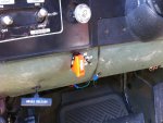
It occured to me that the Slave connector on the front would be perfect for a disconnectable welding setup. So I picked up a junk slave cable and connected two 0 awg cables to it. I disconnected the slave jack cables from the posive and negative junction box and connected them to the alternator. See the picture below.
The only difference between our alternator and the one they used on this website, as far as I can tell, is that ours is isolated. In other words it has an independent ground.
Well at idle. My weldernator was putting out around 30v dc. At 2500 RPM it puts out 120V dc. I rigged up a coat hanger to hook onto the throttle at the injection pump, I really need to come up with a better hand throttle, but it worked for testing.
I tried to weld something and it works great!!! (The following sections in orange were written after my initial attempt, afterwards I tried again and I had no issues, so it must have been a bad connection I was using jumper cables after all. ) [and I was getting nothing. so I put a volt meter to it and the voltage was bouncing up and down. I'm not sure why. Suddenly it occured to me that the slave jack connector is metal and connected to a metal mount. Another works I was connecting the independent ground to vehicle ground. Now why that is a problem I don't know, but I decided to connect directly to the alternator for ground and disconnect the slave jack ground. (the picture shows how it was wired while connected to the slave jack. )]
Well it worked! I welded a bead using a 1/16" 6011 rod. I welded at as little as 1500 rpm, and as high as 2500 rpm. At 1500 rpm the voltage was 60 or 70 volts dc, and the 1/16" rod was the right choice. At 2500 the 1/16" rod melted and fell out of my rod holder (jumper cables clamp) before I could finish the rod. I.E. an 1/8 inch rod would be a good choice.
So Amperage control is via RPM. Frankly it's a little disconcerting to have your truck running at 2500 rpm while parked. I realize that's well short of redline, but still it makes you nervous. 1500 rpm on the other hand is much more tolerable, and 1/16" rod should be fine for a short term repair.
[Do you guys understand why this is happening or if there is another way to fix it? I figured the isolated ground only served for charging on the 24v system. I didn't think tieing it to ground would make a difference. I'm almosted tempted to try it again, I only tried it once like this. ]
Oh as far as the switch goes, next to the safety switch which controls the weldernator is my glow plug switch, up connects the GP controller card and is therefor automatic, center is off, and down is a momentary switch for manual control of the glowplugs. The reason I burned up my GP controller card before is because I had two switches and I accidently switched both at the same time. ( well thats the cause as near as I can tell)
I decided to repurpose the driverside alternator since my cucv has been converted to 12v anyway it no longer served any purpose.
I've been reading about converting an alternator to a welder at the following site.
On-Board Welder
So this isn't my idea, but it seemed to me that the hard part was mounting an extra alternator. For us this was already done.
So I performed the modifications to the alternator and wired it up per the wiring diagram, this is al very simple stuff.
It occured to me that the Slave connector on the front would be perfect for a disconnectable welding setup. So I picked up a junk slave cable and connected two 0 awg cables to it. I disconnected the slave jack cables from the posive and negative junction box and connected them to the alternator. See the picture below.
The only difference between our alternator and the one they used on this website, as far as I can tell, is that ours is isolated. In other words it has an independent ground.
Well at idle. My weldernator was putting out around 30v dc. At 2500 RPM it puts out 120V dc. I rigged up a coat hanger to hook onto the throttle at the injection pump, I really need to come up with a better hand throttle, but it worked for testing.
I tried to weld something and it works great!!! (The following sections in orange were written after my initial attempt, afterwards I tried again and I had no issues, so it must have been a bad connection I was using jumper cables after all. ) [and I was getting nothing. so I put a volt meter to it and the voltage was bouncing up and down. I'm not sure why. Suddenly it occured to me that the slave jack connector is metal and connected to a metal mount. Another works I was connecting the independent ground to vehicle ground. Now why that is a problem I don't know, but I decided to connect directly to the alternator for ground and disconnect the slave jack ground. (the picture shows how it was wired while connected to the slave jack. )]
Well it worked! I welded a bead using a 1/16" 6011 rod. I welded at as little as 1500 rpm, and as high as 2500 rpm. At 1500 rpm the voltage was 60 or 70 volts dc, and the 1/16" rod was the right choice. At 2500 the 1/16" rod melted and fell out of my rod holder (jumper cables clamp) before I could finish the rod. I.E. an 1/8 inch rod would be a good choice.
So Amperage control is via RPM. Frankly it's a little disconcerting to have your truck running at 2500 rpm while parked. I realize that's well short of redline, but still it makes you nervous. 1500 rpm on the other hand is much more tolerable, and 1/16" rod should be fine for a short term repair.
[Do you guys understand why this is happening or if there is another way to fix it? I figured the isolated ground only served for charging on the 24v system. I didn't think tieing it to ground would make a difference. I'm almosted tempted to try it again, I only tried it once like this. ]
Oh as far as the switch goes, next to the safety switch which controls the weldernator is my glow plug switch, up connects the GP controller card and is therefor automatic, center is off, and down is a momentary switch for manual control of the glowplugs. The reason I burned up my GP controller card before is because I had two switches and I accidently switched both at the same time. ( well thats the cause as near as I can tell)
Attachments
-
 62.4 KB Views: 113
 -
 9.5 KB Views: 109
 -
 68.4 KB Views: 75
 -
 101 KB Views: 73
Last edited:
