• Steel Soldiers now has a few new forums, read more about it at: New Munitions Forums!

  • Microsoft MSN, Live, Hotmail, Outlook email users may not be receiving emails. We are working to resolve this issue. Please add support@steelsoldiers.com to your trusted contacts.


TM and Wiring question for MEP701A/16B

MidKnightBomber

New member
42
0
0
Location
Salt Lake City, Utah
I have two questions that I hope will be pretty straight forward

Question #1-what errors are in the MEP701A/16B technical manuals that would affect my ability to properly hook up my Genset as back up power to my house?

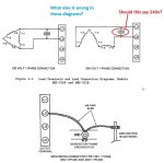
Question #2-looking at the picture I have attached that comes straight out of the technical manual.....I am wondering how the two set ups are different on the load terminals? The left diagram is titled such that the output is supposed to be 120v, 1 phase. The right side diagram is titled such that it is supposed to output 240v, 1 phase. Yet BOTH images SHOW 120v between load terminals L1 and L2. How is this different between the two diagrams? I am suspecting an error in the TM. Can someone set me straight?

Thanks in advance,
I have read and read and read and am currently scheduling my electrician to come to my house to hook this stuff up and I feel this May be some of the final stuff I am "hopefully" lacking.

ImageUploadedByTapatalk1410747240.127038.jpg
 

MidKnightBomber

New member
42
0
0
Location
Salt Lake City, Utah
Regarding question#2....when the generator is set up for 240v, 1 phase:

I assume the voltage between L1 and L2 should be 240v and the voltage between L1 and L0 should be 120v and so also should the voltage between L2 and L0 be 120v. Am I correct and the image in the TM wrong?
 

rustystud

Well-known member
9,071
2,388
113
Location
Woodinville, Washington
It looks like the diagram is missing the other half on the 240 volt one. It looks like half of a zig-zag pattern. Do you have 12 leads coming out of the generator ?
 

goldneagle

Well-known member
4,428
858
113
Location
Slidell, LA
It looks like the diagram is missing the other half on the 240 volt one. It looks like half of a zig-zag pattern. Do you have 12 leads coming out of the generator ?
These generators have selector switch that changes the configurations. There are no wires to reconfigure. (just the terminals you see in the diagram)
 

Isaac-1

Well-known member
1,970
48
48
Location
SW, Louisiana
There are a number of major mistakes in the MEP-016B / MEP-701a TM's , the 120V box in the 240V single phase connection diagram is just one of them. Also note this is pure 240V by the book, not 120/240V split single phase, altough it seems many, but not all of these generators were modified (without documentation) to output 120/240V split single phase when set to 240V single phase. (I think bringing neutral out of L0).

Also be aware the wiring schematic diagram inside the top of the control box on these are also somewhat fictional.

As to hooking up to your house, I would highly suggest hooking it up in 120V only mode, unless you have a particular need for 240V such as a well pump. Given that these generators only output 16 amps at 240V they can't supply enough power to run most 240V home appliances. And running in the non-documented 120/240V split single phase mode, does cut your available blocks of 120V power in half, (instead of one big block of 32 amps at 120V you get 2 blocks of 16 amps at 120V, L1- to neutral, and L2-neutral) increasing the chances of overloading one set of windings if you have an out of balance load.
 
Last edited:

FloridaAKM

Well-known member
2,699
392
83
Location
Gainesville, Florida
That might explain why I burned up my Direct TV system when I hooked the MEP-016B genset to my home during a hurricane outage years ago. I may have to revisit the old genset & use it as a 110v only power source, instead of trying to let the breaker panel split the load!

Good luck with your system!
 

MidKnightBomber

New member
42
0
0
Location
Salt Lake City, Utah
There are a number of major mistakes in the MEP-016B / MEP-701a TM's , the 120V box in the 240V single phase connection diagram is just one of them. Also note this is pure 240V by the book, not 120/240V split single phase, altough it seems many, but not all of these generators were modified (without documentation) to output 120/240V split single phase when set to 240V single phase. (I think bringing neutral out of L0).

Also be aware the wiring schematic diagram inside the top of the control box on these are also somewhat fictional.

As to hooking up to your house, I would highly suggest hooking it up in 120V only mode, unless you have a particular need for 240V such as a well pump. Given that these generators only output 16 amps at 240V they can't supply enough power to run most 240V home appliances. And running in the non-documented 120/240V split single phase mode, does cut your available blocks of 120V power in half, (instead of one big block of 32 amps at 120V you get 2 blocks of 16 amps at 120V, L1- to neutral, and L2-neutral) increasing the chances of overloading one set of windings if you have an out of balance load.
Isaac,

You are correct, My plan is to run dedicated 120V, 1Phase to the house for the exact reasons you mention, that way I can get the full 30+Amps out of the generator (unless the electrician has a strong argument otherwise). I have no need to use 240v for emergency use in the house.

I am only concerned about the wiring diagram in the TM in case I desire to ever use the Generator as a stand alone devise on some 240v equipment. Right now I am hooking it up to the house, but want to make sure I am not working on false info from a typo filled TM.

Even though my two questions seem related, in reality they are not related since I am not hooking it up to the house in 240V. Apologies for any confusion. I am just trying to make sure I have captured and corrected all of the errors in my copy of the TM that may mislead my electrician (or myself) when he comes over to help me connect it. I plan to use him as the electrical expert but I will need to be the one that fully understands the MEP so that he doesn't treat it like a normal civilian Generator.

If the diagram has an issue then I would like to PEN in the correction into my hard copy of the Technical manual. See the attached Photo.

Is the 240v correction the only correction I need to make in this photo? (From the TM).


TM copy.jpg
 
Last edited:

Isaac-1

Well-known member
1,970
48
48
Location
SW, Louisiana
I think the rest is correct, note that the ground jumper to the grounding point is often already installed, but is usually connected to the back side of the output lug inside the control box, not the outside connector point. Also that grounding of L-2 would be correct for a 240V only 2 wire system, but would NOT be correct for a 120/240V split single phase where you would want the neutral grounded. As to arguments against wiring it to the house in 120V only mode the biggest one tends to be the potential for under sized neutrals in your breaker box on shared return neutral circuits. If you are planning on wiring in a whole home transfer switch this might be an issue, but if you are just wiring in a transfer sub panel, you (he) can check the individual circuits for undersized neutrals as they are hooked up, and make sure not to hook any two up that share an under sized neutral. Hopefully this would not mean having to choose between hooking up the outlet for the refrigerator or hooking up the outlet for the microwave (or running a new larger neutral). If you are wiring it up to a whole house transfer switch and have under sized neutrals, an alternative compromise here is to only hook it up to one side of the box (gen L1 - house L1, gen L2 - house L0, but nothing to house L-2 in 120V 1 phase only mode, or vice versa) this would only provide power to half the outlets in the house, and might mean having to move some breakers around for all important loads to be on the powered half, but I think should work.
 

MidKnightBomber

New member
42
0
0
Location
Salt Lake City, Utah
I don't think I would know the first thing about wiring this unit up to my home as a 120/240V split single phase since it is as you said "is pure 240V by the book, not 120/240V split single phase"

Therefore, even if I wanted to hook it up as 240v to my home, If I only have one wire that is 240V...how would I wire it to my house which has two wires as 120v? (i.e. 120/240V split)
 

Isaac-1

Well-known member
1,970
48
48
Location
SW, Louisiana
Modified by the Military? Or Joe the Plumber?
By the military, but none seem to show any modification markings for this, and no one that I know of has found documentation on it. This change may have even happened during the production run. From casual survey of owners online it seems at least 80-90% are really 120/240 split single phase
 

Isaac-1

Well-known member
1,970
48
48
Location
SW, Louisiana
The easiest way is to switch the reconnection switch inside the control box to 240V single phase (engine must be off when switch is turned), and with the output breaker turned on use a multi meter measure to see that you get 240V between L1 -L2 and 120V between L1 and L0 as well as between L2 and L0. on the output lugs. Then you need to confirm this is not a phantom voltage by running test load between L0 and L1, a cheap incandescent lightbulb in a closet socket fixture makes a good test, just wire it right to the lugs (total cost for the test setup should be under $5 if you don't have stuff laying around (an old lamp, etc.).
 

MidKnightBomber

New member
42
0
0
Location
Salt Lake City, Utah
The easiest way is to switch the reconnection switch inside the control box to 240V single phase (engine must be off when switch is turned), and with the output breaker turned on use a multi meter measure to see that you get 240V between L1 -L2 and 120V between L1 and L0 as well as between L2 and L0. on the output lugs. Then you need to confirm this is not a phantom voltage by running test load between L0 and L1, a cheap incandescent lightbulb in a closet socket fixture makes a good test, just wire it right to the lugs (total cost for the test setup should be under $5 if you don't have stuff laying around (an old lamp, etc.).
Great suggestion
Thanks Isaac
 

MidKnightBomber

New member
42
0
0
Location
Salt Lake City, Utah
By the way, I know the generator is military rated at 3KW at 8,000ft elevation, but realistically at 4500ft elevation what can I expect to get out of it? 4kw? 4.5kw? Or should I always keep it within the 3kw range and the range of the load meter?
 

Isaac-1

Well-known member
1,970
48
48
Location
SW, Louisiana
Hard to say higher elevation means the engine looses power, but also mean the air can't conduct heat away as fast either. I would guess in the real world you can probably sustain a load of 3.5 to 4 KW, but that is just a guess and don't blame me if the magic smoke escapes.

Ike

p.s. a normally aspirated diesel engine looses 3-4% of its power per thousand feet of altitude, but of course the military put massively over sized engines on these generators, so ....
 
Last edited:
Top
AdBlock Detected

We get it, advertisements are annoying!

Sure, ad-blocking software does a great job at blocking ads, but it also blocks useful features of our website like our supporting vendors. Their ads help keep Steel Soldiers going. Please consider disabling your ad blockers for the site. Thanks!

I've Disabled AdBlock
No Thanks