• Steel Soldiers now has a few new forums, read more about it at: New Munitions Forums!

  • Microsoft MSN, Live, Hotmail, Outlook email users may not be receiving emails. We are working to resolve this issue. Please add support@steelsoldiers.com to your trusted contacts.

tractor W/ removable bed over 5th wheel? has anyone done this?

jdknech

Active member
1,095
6
38
Location
Jeffersonville, Indiana
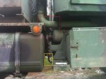
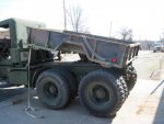
pic #1- red box is where the pump is mounted on the inside of the frame rail, yellow box is one of the lines to the pump
pump pic.jpg
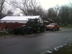
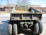
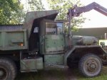
pic #2- over all view of the rear/side of the truck
085.jpg
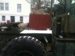
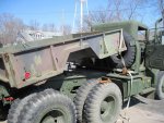
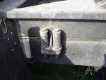
pic #3- hydraulic tank i mounted here because where it was mounted interfered with the super singles (this truck was originally a A0 so it had duals) 087.jpg

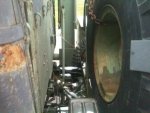
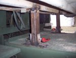
pic #4 where i could move the tank to, so i could gain more room 089.jpg
 

quickfarms

Well-known member
3,495
25
48
Location
Orange Junction, CA
You can replace the military fifth wheel with a civilian one to lower the bed. You san also replace the bed floor over the fifth wheel with a steel plate and king pin.
 

MWMULES

Well-known member
Steel Soldiers Supporter
In Memorial
5,580
349
83
Location
DESOTO, KANSAS
i like it! now if i can think outside the box- could this be made into a "light duty" dump bed? i already have the hydraulic power because of the winch on the front.. could i mount 2 cylinders, one on the outside of each frame rail... and the rear of the bed hinged on the shackel mount... and when not needed, i could un-pin the rear of the bed, and remove the cylinder mount pins from the frame, and lift the whole thing off? (Quick disconnect hydraulic lines)
You might want to beef up the bed frame or bigger king pin plate, but the way I did it is a natural dump. The normal ride of the bed is below and you have to really pull to get the front end down. I ended up securing mine with hitch pins up front and swing out angles on the back. Only used it as a dump once and had them load the rear.
 

Attachments

zebedee

conceptualizer at large
Steel Soldiers Supporter
1,651
815
113
Location
Central NY
Your more then welcome to if you want. But I think I understand exactly what your saying! And it's nothing short of genius!
If you go for legs, remember that as the bed comes off, or more correct, as the truck pulls out from under the bed, there will be 'pulling' on the rear legs, conversly, as it is put on the bed, there will be 'pushing' of the rear legs. So a stiff leg or brace will be needed from the foot of the leg to the body**. The other force to be resisted or overcome will be the force needed to 'engage' the fifth wheel lock. Have you ever seen an overzealous semi driver "crash" load the trailer against the trailer brakes! The easiest sollution would be nudging up against the nearest tree or building, to finish the loading and push the King-pin into the 5th wheel jaws. Alternatively, a 'Come-a-long' behind the cab could be used.


The front legs will not have this as they are not put on the ground untill the bed is lifted completely off of the truck frame.

Tructor body legs.jpg Tructor body removal.jpg

NB. The rear legs can't be put on the back of the bed as the braces** would clash with the rear cross member of the truck.

OK - Next problem please!
 
Last edited:

Robo McDuff

In memorial Ron - 73M819
Steel Soldiers Supporter
2,892
1,520
113
Location
Czech Republic
With hitching the dump bed with king plate into the 5th wheel jaw. Backing up into stuff might not always be possible and lacks a certain elegance. What about using the winch or add a small dedicated extra winch to hook into the bed and pull it up tight, maybe even with an automatic switch-off when the jaw engages.
 

Robo McDuff

In memorial Ron - 73M819
Steel Soldiers Supporter
2,892
1,520
113
Location
Czech Republic
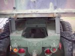
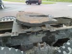
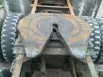
Something kept nagging why I abandoned this road earlier for the M51A2 and I finally figured out what it was: the fifth wheel is as wide or wider as the primary frame.


2011 07 July 13 _resize.jpg 2011 07 July 14 _resize.jpg

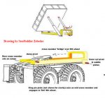
Zebedee, on your drawings if you look good, I think the sub-frame also runs to the outside of the primary frame. (hope you don't mind that I included your drawing)


tructor dump buildup-crop.jpg

It means that, if you want to have this construction, you have to make a very solid construction to the side of the main frame to support the slidable sub frame with a loaded dump bed on top.

The alternative is using only the rear part of the sub frame and let it rest on the main frame. The problem with that is that the main frame has all these rivets sticking out. On the original M51 dump truck, there is a wooden separator with holes for the rivets between these frames. You could use that as well, makes sliding into the 5th wheel even smoother, but you first need to fix the wood onto the main frame; it normally is laying lose and is kept in place by the rivets and the weight of the dump bed on top of it.

Unless you have mv-surplus trailers, I would install a civil 5th wheel. They are lower and don't need the rear ramps.

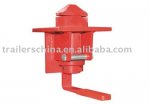
On every set-up the problem is to securely lock the stuff in place. I now have 10 bolts to keep the 5th wheel in place and 12 bolt to keep the dump unit in place. Undoing them and redoing them is a PITA. I am now looking into using twistlocks for containers.

Twist_lock.jpg

Four of these on a container trailer will hold a 30-ton container in place! Details of how to do that I will figure out this spring when we will continue with restoration, but its something I am already kicking around.


http://www.youtube.com/watch?v=zHdiCzNtHkg&NR=1

In work:

http://www.youtube.com/watch?v=pGlPROG87uc&feature=player_detailpage
 

zebedee

conceptualizer at large
Steel Soldiers Supporter
1,651
815
113
Location
Central NY
Something kept nagging why I abandoned this road earlier for the M51A2 and I finally figured out what it was: the fifth wheel is as wide or wider as the primary frame.

Zebedee, on your drawings if you look good, I think the sub-frame also runs to the outside of the primary frame. (hope you don't mind that I included your drawing.)

It means that, if you want to have this construction, you have to make a very solid construction to the side of the main frame to support the slidable sub frame with a loaded dump bed on top.

The alternative is using only the rear part of the sub frame and let it rest on the main frame. The problem with that is that the main frame has all these rivets sticking out..........

Challenge Accepted!
 

Robo McDuff

In memorial Ron - 73M819
Steel Soldiers Supporter
2,892
1,520
113
Location
Czech Republic
Would be interesting to see what you come up with. :idea: :eek:

I had some problems trying to get this to work. The main and insurmountable problem was that I had to get this truck road-certified and the Netherlands have very very restrictive rules what you can do in changing anything on the main frame. If it would not have been for the fact that our truck was considered hobby veteran AND destined for export as museum object I never would have gotten away with drilling holes in the frame from above and adding the fifth wheel the way I did.

Any design to make a permanent 5th wheel and swappable dump bed would have run into too much problems on the legal side before even starting any practical work. For one, in the beginning the Dutch DoT wanted a certified approval including frame strength calculation and brake details from the original manufacturer to replace the original pintle for the civic fish-mouth trailer connection and for how to mount the fifth wheel and the weight restrictions for both constructions. With the manufacturer not existing anymore, I could get the certificate from a Dutch coach or truck builder (DAF) as well. Off course, they would first have to do research on the original frame used, make strength calculations etc etc $$$$$$$$$.

In the end, the Dutch DoT loosened up a bit for me and used a combination of details of the original TM ...10 I showed them and the engine specifications. But that was only for switching between fully bolted fixed original dump truck status and a fully-bolted fixed 5th wheel tractor status. They made it very clear that any more complicated swappable structures like discussed in this thread or I had thought about at that time were still-born ($$$ and paper-wise). And that I should get out of their testing station very quickly and never come back before they changed their minds about the fixed swap as well :wink:.
 

quickfarms

Well-known member
3,495
25
48
Location
Orange Junction, CA
There are rules here in the US about what you can and can not do to trucks.

Drilling the top and bottom frame flange is a no no. Also welding to the frame can be an issue.

These issues are greater for commercial trucks than our historic vehicles.

A lot if the bobbed trucks would Have an issue with a DOT inspection. I do not understand why the do not use the rear suspension from a commercial vehicle.

Could you have installed a commercial swap body system on your truck? I have looked at some if the clamps an they look like they would work for a removable bed.
 

Robo McDuff

In memorial Ron - 73M819
Steel Soldiers Supporter
2,892
1,520
113
Location
Czech Republic
There are rules here in the US about what you can and can not do to trucks.

Drilling the top and bottom frame flange is a no no. Also welding to the frame can be an issue.

These issues are greater for commercial trucks than our historic vehicles.

A lot if the bobbed trucks would Have an issue with a DOT inspection. I do not understand why the do not use the rear suspension from a commercial vehicle.

Could you have installed a commercial swap body system on your truck? I have looked at some if the clamps an they look like they would work for a removable bed.
First time I hear about the US having such rules as well. Drilling into the top flange was the problem, but because
A: the holes where on the strengthening triangle\
B: the fifth wheel would have this spacer plate below it giving additional strength
the Dutch DoT decided that in this specific case I could continue. To be clear, I consulted with the Dutch DoT after the first inspection (as dump truck) and before the second inspection (after repairing the bad points and making the swap) with all the drawings and TMs several times before even removing the dump bed to make sure they allowed what I wanted to do.

As to the commercial swap body system, that could have worked but there would have been another problem. As it was now, they gave me a so-called vehicle homologation stating the date of manufacturing as 1973. Basically, the M51A2 and the M52A2 existed in this configuration in 1973. That means, the truck has to fulfill the rules for trucks from 1973 (specially regarding emission and brakes).

However, installing a modern swappable body system would make a new truck that did not existed in 1973. So the date of manufacturing would change to 2011 because it would be more or less a "new" type. Which means having to fulfill the 2011 rules regarding emission, brakes etc etc. No way that truck would ever pass the 2011 inspection requirements without major $$$$$$$$ investments. ON top of that, the truck would lose it's veteran status (25 years +) and I would have to pay full price on insurance and taxes. Not a nice option.
 

zebedee

conceptualizer at large
Steel Soldiers Supporter
1,651
815
113
Location
Central NY
Something kept nagging why I abandoned this road earlier for the M51A2 and I finally figured out what it was: the fifth wheel is as wide or wider as the primary frame.
Robo - a narrower civi plate would help both in width and height, but if you want to keep the military 5th wheel then here are my first thoughts on "wide 5th plate" etc. ...
tructor dump buildup 2.jpg

Will expand on detail but I need to know if there is enough clearance between the inner dual and the frame under full axle articulation for the red frame side extensions and the yellow dump sub-frame....
 

Robo McDuff

In memorial Ron - 73M819
Steel Soldiers Supporter
2,892
1,520
113
Location
Czech Republic
That looks good but...

In the Netherlands, I am allowed only to drill in the middle zone of the side flange of the main frame and the bolts should not be completely at the lower end of the side-rail; more or less in the middle is the best.

Together with the DoT, I looked at that idea for a side rail as you drew as well for mounting the 5th wheel (much easier for swapping).

The end conclusion was that you would need at least a 3 inch high high-quality steel side-rail, 4 inch would be better. You also have to put spacers between it and the frame to go around those @#$#@ handles (or take those off), the support brackets, and the rivets for the frame cross-beams. Seeing all those bolts and rivets already there, and seeing the civic European solution and the standard M818 set-up, they agreed that 5 holes from above would be the better way to go.

Pic 1: civic standard EU side rail for fixed or movable 5th wheel. Watch how high this rail is. Installing that on this existing frame following Dutch rules is a serious pain.
Pic 2: side rail fixed to an M818 tractor. The rail actually is quite small and sits very high on the main frame to go around the handles and support brackets. That was not acceptable for the Dutch DoT.
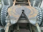
Pic 2: my M51A2 preparing for fitting the 5th wheel. On the top part of the photo you see the spacer wood that normally rests between main frame and sub frame of a dump truck. You see the six bolts for connecting the spacer plate. In the end, we used only 5; the last bolt from the back (left side of picture) was left out. Too much rivets around it and two bolts there would not have been much better than only one.
5th wheel detail 05cr.jpg M818 2rc.jpg fixing 5 wheel uni -r.jpg


To go back to the hydraulics mentioned earlier. One way of maybe simplifying the hydraulic problem would be using a central front telescopic cylinder. You would have to strengthen the bed but it would at least stop the cylinders from interfering with the fifth wheel or running outside the frame and interfering with the wheels when off-road.

telescopic_hydraulic_cylinder_s.jpg
 

zebedee

conceptualizer at large
Steel Soldiers Supporter
1,651
815
113
Location
Central NY
That looks good but...
In the Netherlands, I am allowed only to drill in the middle zone of the side flange of the main frame and the bolts should not be completely at the lower end of the side-rail; more or less in the middle is the best.
100% agree - that's why the right half of the pic (before) has those handles and the left half (after) doesn't - plan A was to utilise existing holes. ZERO drilling of new holes. Maybe reaming out a size or two that's all.

Together with the DoT, I looked at that idea for a side rail as you drew as well for mounting the 5th wheel (much easier for swapping).
Yes - side rails (in red) are for guiding and stiffness of the sub frame (yellow)

The end conclusion was that you would need at least a 3 inch high high-quality steel side-rail, 4 inch would be better. You also have to put spacers between it and the frame to go around those @#$#@ handles (or take those off), the support brackets, and the rivets for the frame cross-beams. Seeing all those bolts and rivets already there, and seeing the civic European solution and the standard M818 set-up, they agreed that 5 holes from above would be the better way to go.
In front of the 5th wheel you could have a stiff 'landing' socket or pad that the sub frame drops onto with the majority of the strength in the subframe not the side rails. [That doesn't read too clear - another sketch I feel...]
Next thought is to only have the front of the subframe widened to go around the 5th wheel enough to release the King pin so that the sub-frame and body lifts up to clear the 5th wheel rather than have the whole front wide enough to slide past the 5th wheel...

Pic 1: civic standard EU side rail for fixed or movable 5th wheel. Watch how high this rail is. Installing that on this existing frame following Dutch rules is a serious pain.
Yeah - that's to be avoided.
Pic 2: side rail fixed to an M818 tractor. The rail actually is quite small and sits very high on the main frame to go around the handles and support brackets. That was not acceptable for the Dutch DoT.
Yeah - handles got to go! or make new with longet threads to accept side rail thickness aswell.

Pic 2: my M51A2 preparing for fitting the 5th wheel. On the top part of the photo you see the spacer wood that normally rests between main frame and sub frame of a dump truck. You see the six bolts for connecting the spacer plate. In the end, we used only 5; the last bolt from the back (left side of picture) was left out. Too much rivets around it and two bolts there would not have been much better than only one.

To go back to the hydraulics mentioned earlier. One way of maybe simplifying the hydraulic problem would be using a central front telescopic cylinder. You would have to strengthen the bed but it would at least stop the cylinders from interfering with the fifth wheel or running outside the frame and interfering with the wheels when off-road.
Yes - single acting cyl up front would work but would have to cut into bed or create space infront of bed...
 
Last edited:

Robo McDuff

In memorial Ron - 73M819
Steel Soldiers Supporter
2,892
1,520
113
Location
Czech Republic
100% agree - that's why the right half of the pic (before) has those handles and the left half (after) doesn't - plan A was to utilise existing holes. ZERO drilling of new holes. Maybe reaming out a size or two that's all.
Taking out the handles would give you four good holes, but you would need at least two or three more in between the support brackets. I am not sure if taking out the rivets holding the cross beam would be an option or highly illegal


In front of the 5th wheel you could have a stiff 'landing' socket or pad that the sub frame drops onto with the majority of the strength in the subframe not the side rails. [That doesn't read too clear - another sketch I feel...]
Please do, they help and I am too lazy to make them myself.

Next thought is to only have the front of the subframe widened to go around the 5th wheel enough to release the King pin so that the sub-frame and body lifts up to clear the 5th wheel rather than have the whole front wide enough to slide past the 5th wheel...
Now we are maybe getting onto something. Never thought about that but that seems a nice idea. It would mean that the side-rails would only extend from the cross beam forward. Combine that with the landing pad mentioned and it might work nicely strength-wise also


Yes - single acting cyl up front would work but would have to cut into bed or create space infront of bed...
replacing dumb bed.jpg

With the M51A2, you have the spare wheel on one side and tool box on the other side. The space is there but you wave to find an alternative place for the spare tire (or go without and use one of the rear doubles as emergency spare).

Another option would be to cut about 10 inches in the front panel of the bed and put the cylinder partly inside the bed body. You would have to make a very solid housing around the cylinder in the bed side to protect it from material being transported but you would need some strengthening anyway to make sure that the cylinder lifts the bed evenly and without torsion. The biggest minus would be that you would not have a straight front in the bed anymore.

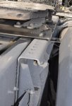
Another thing would be that you probably would need some extra strengthening of the frame on that place. From the pic on left below you can see that there are two vertical cross beams, in front of the fifth wheel. One is where the dumb bed sub frame is connected to the main frame (detail pic right). The second cross beam is more forward under the rear of the cabin. In between you would need a solid construction to hold the cylinder and carry the weight of the dump bed being raised. You can install that cylinder permanent on the main frame but able to turn forward and backward. That way, you can maybe use it as well for lifting pulling the whole dump unit from its resting stamps onto the truck itself or push it off? Have to think about that one, lots of options with hydraulics.


2011 07 July 14 _resize.jpg S5031874_resize.jpg
 
Top