• Steel Soldiers now has a few new forums, read more about it at: New Munitions Forums!

  • Microsoft MSN, Live, Hotmail, Outlook email users may not be receiving emails. We are working to resolve this issue. Please add support@steelsoldiers.com to your trusted contacts.

Trouble with mile marker winch installation

erasedhammer

Active member
843
56
28
Location
Maryland
I have a couple questions, and no these are not the normal ones that can be solved by a manual, I already have the installation instructions.

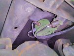
1. I have the A2 harnesses in and there appears to be a third male connector right by the horn wires.
No place for it to plug in, maybe the A2s had this connector for the 24v for the winch? (If so I assume this replaces the spliced power coming off the temp sensor)

2. I know of the trick to get the a frame bolts flipped around but I am having trouble. I jack the arm up (right under the spring) and test if the bolt is loose. Got probably an extra 8 inches up and the bolt still wasn't loose.
The nut is still on it, should I take that off prior to jacking it up? Or does it matter, cause I have a 2 ft breaker bar on it and the but isn't budging.

3. Also, is the winch bracket made of hardened steel? The holes are off on mine and I need to redrill them, wondering if I should go get some carbide drill bits.


Extra harness connector:
14942859579231233508003.jpg
 

3000gt

New member
177
0
0
Location
hernando ms
1) horn wire? Why are u plugging it in there? Look for the wire going to the coolant temp sensor
2) jack a little and hit bolt with nut on bolt once u have old bolt half way off, take new bolt and come from the rear and drive it out
3) loosen your brackets should be 4 bolts and see if the line up. Brackets may be bent
 

erasedhammer

Active member
843
56
28
Location
Maryland
1) horn wire? Why are u plugging it in there? Look for the wire going to the coolant temp sensor
2) jack a little and hit bolt with nut on bolt once u have old bolt half way off, take new bolt and come from the rear and drive it out
3) loosen your brackets should be 4 bolts and see if the line up. Brackets may be bent
1. There are only two wires that are supposed to be down at the horn, for some reason there's a third mystery wire as you see in the picture.
3) brackets are about 2 inches off they are just in the wrong place so I have to drill another set of holes next to the existing holes on the winch
 

porkysplace

Well-known member
Steel Soldiers Supporter
9,604
1,486
113
Location
mid- michigan
1. There are only two wires that are supposed to be down at the horn, for some reason there's a third mystery wire as you see in the picture.
3) brackets are about 2 inches off they are just in the wrong place so I have to drill another set of holes next to the existing holes on the winch
There is a metal tag on the wire get the number off it and locate it in the wiring diagram. Then you will know what it is for.
 

doghead

4 Star General /Moderator
Staff member
Super Moderator
Steel Soldiers Supporter
26,247
1,168
113
Location
NY
Don't you already have a thread on the winch bracket?
 

doghead

4 Star General /Moderator
Staff member
Super Moderator
Steel Soldiers Supporter
26,247
1,168
113
Location
NY
Well, I don't want to talk about it either, but I keep asking you to stop posting new threads every time you think of something(when you have thread started on the same topic/project)

I've asked you several times to continue a thread, not make a new one every time.


Get it together...
 
Last edited:

erasedhammer

Active member
843
56
28
Location
Maryland
Well, talk about it or you loose the privilege to post.

I've asked you several times to continue a thread, not make a new one every time.

Maybe one of the other mods will approve your posts and manage your threads for you in the future.
Dude. I'm not here to talk about any other thread. I was asking a different question, and to be frank, that thread is old enough I doubt anyone would bother to respond to some added piece of info in an old thread. Trust me, I've done it and had no one reply simply because it's been silent for a couple months.
I have said I will stop crossing over threads and I have.
 

juanprado

Well-known member
Steel Soldiers Supporter
5,520
2,740
113
Location
Metairie/La (N'awlins)
The bolt just needs to ease out as friction is keeping in place. Douse with wd40. Use the new bolt to gently tap out the other one at the same time. Just needs weight off of it - does not have to be that high.

That 3rd wire I suspect is for the back up lights for an ambulance model as they feed from there as controlled by the master light switch/blackout.

generic numbering chart here:
http://www.steelsoldiers.com/showthread.php?163769-Military-Wire-ID-tag-master-code-list


Last edited:

erasedhammer

Active member
843
56
28
Location
Maryland
The bolt just needs to ease out as friction is keeping in place. Douse with wd40. Use the new bolt to gently tap out the other one at the same time. Just needs weight off of it - does not have to be that high.

That 3rd wire I suspect is for the back up lights for an ambulance model as they feed from there as controlled by the master light switch/blackout.

generic numbering chart here:
http://www.steelsoldiers.com/showthread.php?163769-Military-Wire-ID-tag-master-code-list


Weight off it... so should I be jacking up the whole vehicle rather than compressing the suspension? What are those nuts torqued down to?
 

erasedhammer

Active member
843
56
28
Location
Maryland
Mile Marker Winch Installation: A Learning Experience...

Just finished up my mile marker winch installation. Instructions on some of the other posts and websites were pretty vague, and I'd thought I'd share what I learned through my speedy 5 hour job.


First I'd like to share some advice on how to properly turn the suspension bolts around. So I've heard all different places about where exactly to put the jack to get the bolt in a loose state, but they were all wrong.
The position that I found worked perfectly was the inward bolt on the spring/shock assembly base plate. I put a hydraulic jack right under that and just jacked the vehicle up little by little (wheel never came more than 1 inch above the ground).Right before the wheel came off the ground and the suspension extended a significant amount, the bolt will literally came loose and you can pull out the bolt with your fingers (nut can be taken off before jacking occurs, takes some effort).The bolt can be taken right out without anything in its place and control arm will stay perfectly aligned. You can turn the existing bolt around or if you have a new one just insert it from the rear (dont take that the wrong way...)
The driver side caliper will get in the way of putting the bolt in the back of the control arm, and the caliper bolts need to be loosened and the whole caliper moved a little. Some say that the bolt can go in without moving the caliper, but I think that's a case by case scenario... The other side bolt doesn't have any problems... super easy.

The drawings about how to route the hydraulic hoses is vague... I routed them down inside the frame above the rotor and calipers and in front of the differential. And just to clarify the hose that the winch replaces is a blue one that goes from the hydro boost down to the steering gear.
The metal tubing attached to the winch itself can be carefully bent to face the differential and the hoses can be easily screwed from below. Hose routing comes pretty close to the rotor, zip ties are your friend.

Also a quick note on the wiring as in a previous post I had a long discussion with someone about how the harness wiring works. I thought I'd explain it the best I can:
There is the main harness (kascar) that has the connector that attaches to the bulkhead in the cab then goes all the way down to the winch itself. There are three connectors on the end of that. Two (very obvious) are the signal that connect to the solenoids on the winch itself. The other one is 24v power that uses a separate cable, for some god awful reason... You just need to cut a custom size wire and connect it up to the that connector on the harness, route it up to a circuit breaker, then from there another wire goes over to the temperature sensor right next the alternator. A Y connector is used to splice 24v off there which then goes and powers the solenoids. And remember the only correct remote control is the yellow one.


If anyone else has anything to add to help people in the future with this installation feel free to post below.

P.S.
Whoever designed the mounting bracket for the A1 brush guard should be fired. There are 3 bolts in close proximity to each other all at 90 degree angles to each other all confined in a cube of metal, the design is horrid and was more frustrating than the suspension bolts.
 
Last edited:
Top
AdBlock Detected

We get it, advertisements are annoying!

Sure, ad-blocking software does a great job at blocking ads, but it also blocks useful features of our website like our supporting vendors. Their ads help keep Steel Soldiers going. Please consider disabling your ad blockers for the site. Thanks!

I've Disabled AdBlock
No Thanks