Universal Wiring for MEP002 and 003
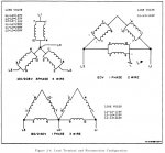
I have been reviewing the TM for the MEP-002 and 003 gensets since I'm going to soon be running one. I have been paying particular attention to the load terminal wiring.
Before I ask my questions, I'd like to give a little overview of my use of the generator will be. My primary use will be to power my camper, which runs on 120V at 30 amps. With the A/C, water heater, and a tv on, it consistenly uses at least 20 amps of power. It uses a 30 amp RV plug for power. However, I would also like to be able to have a pair of duplex 110v outlets and a 220V outlet available for use.
So, keeping my desires in mind, I turn to the specifications and Load Terminal Configuration diagram. The specifications says for 120 1 phase, it can do 104 amps and in 120/240 1 phase mode, it can do 52 amps. 52 amps is more than enough to power my single largest load (my camper), but, it also says to not load the legs to more than 5% difference between legs. That means I'd have to keep at least 27 amps of load on the other leg, which isn't feasible, so to run the camper in 120V mode when running the camper. No problem, I won't likely have to power any 240 volt loads while also powering the camper so I can run in 120V mode.
So, now the question comes in how to configure these outlets to provide the most versatility without burning up coils in the generator and without accidentally feeding twice the rated voltage into my camper. To run in 120V mode, I'm supposed to get my hot from L3 and my neutral from L1.
But, when I switch the genset into 120/240V mode, the L3 to L1 connection becomes 240V, and to get 120, I have to go to either L0 to L1 or L0 to L3. I cannot come up with any 1 wiring configuration that does not require me to rewire the load terminals to support my varying loads.
Any ideas? I'm still a little ways away from building this out, but I'm trying to figure out the logistics now.
Attachments
-
62.2 KB Views: 86
Last edited:


