• Steel Soldiers now has a few new forums, read more about it at: New Munitions Forums!

  • Microsoft MSN, Live, Hotmail, Outlook email users may not be receiving emails. We are working to resolve this issue. Please add support@steelsoldiers.com to your trusted contacts.

Vic 1 Radio Power

jeffhuey1n

SMSgt, USAF (Ret.)
Steel Soldiers Supporter
1,890
1,480
113
Location
Laramie County, Wyoming
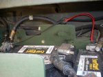
After extensively researching the installation of the vic 1, I have sufficient information, I think, to install my system, many thanks to all the posts throughout this site! Here's the problem: Power. I think the wiring to the batteries is wrong but can't find the correct wiring diagram which shows where the individual wires go. Usually red means power and black means ground...this truck has all 4 wires going the the positive side (see picture)

Correction: After digging around in the battery compartment, two red wires go to the POS on the right of the first picture and two black wires go to the NEG on the left side of the picture.

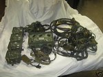
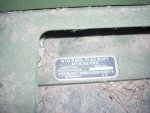
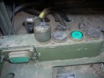
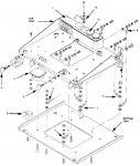
The attached pictures show the mount under the pax seat, the model of the mount and the wiring to the batteries. The red and black wires are supposed to power the mount. And finally the system.

So my question is: do the red wires go to POS and the black to NEG? Or is it wired correctly and I've got other problems?
 

Attachments

Last edited:

wsucougarx

Well-known member
6,951
67
48
Location
Washington State
What kind of radio are you using? Are you using a VRC-12 based radio? (RT-524, RT-246, PRC field radio)
I do have a suggestion on your setup. I'd incorporate a suppressor of some type to your system. The voltage flucuations from your truck could ruin your VIC-1 and radios. The MX-7777 type suppressors are the most popular for this application.
I have a CX power cable and it is marked negative for the green/black and positive for the red/brown
 

jeffhuey1n

SMSgt, USAF (Ret.)
Steel Soldiers Supporter
1,890
1,480
113
Location
Laramie County, Wyoming
No radio is installed. Just the mount with the power cord running to it and a speaker behind the PAX seat with a wire that'll fit into a crew members control box. I'll get the number off the power cable and post it. Sounds like I'll need to check the wiring where they come out to the battery and see what colors go where...

Where would I get a suppressor and how does it get incorporated into the system?
 

wsucougarx

Well-known member
6,951
67
48
Location
Washington State
I got my suppressor off of ebay. Basically your battery power goes directly to the suppressor. It has a circuit breaker in it to protect your intercom and radio equipment. From the MX-7777, you power your AM-1780 and your radio mounts. That radio mount you have is for a SINCGARS based radio I believe. If you plan on a VRC-12 based radio then you'll need the MT-1890 radio mount
Here's a link to a suppressor:
MILITARY RADIO SUPPRESSOR MX-7777 B / GRC - eBay (item 360209925785 end time Jun-18-10 14:57:01 PDT)
 

jeffhuey1n

SMSgt, USAF (Ret.)
Steel Soldiers Supporter
1,890
1,480
113
Location
Laramie County, Wyoming
The cable number is CX-13302/VRC. My field of expertise isn't electronics. When it comes to radios if it doesn't have an on/off switch I'm in trouble.

Do I have to have the radio in order to get the vic 1 working?
 

wsucougarx

Well-known member
6,951
67
48
Location
Washington State
You do not need a radio for the VIC-1 system. If you would like to use your radio through the VIC-1 then you do need to hook a CX-4723 cable b/w your mount and the AM-1780 intercom box
 

jeffhuey1n

SMSgt, USAF (Ret.)
Steel Soldiers Supporter
1,890
1,480
113
Location
Laramie County, Wyoming
In a nutshell then, this is a plug and play system as long as the power supply is correct, if I understand correctly. Unplug the power cord from the mount, plug it into the AM-1780 and connect all the other components. Turn on the power switch, cross your fingers and hope it works. Sound about right?
 

cranetruck

Moderator
Super Moderator
Steel Soldiers Supporter
10,350
75
48
Location
Meadows of Dan, Virginia
Be careful with the wiring if you don't use the MX7777, it provides reverse polarity protection as well and the VIC-1 system will be damaged if the polarity is not correct...
 

jeffhuey1n

SMSgt, USAF (Ret.)
Steel Soldiers Supporter
1,890
1,480
113
Location
Laramie County, Wyoming
Thank you. I'll find one of the MX7777's. More questions: There are four pins for the power plug A, B, C and D. When I check for power with a multimeter, I get 25.1 VDC between A and B. I get nothing anywhere else. Am I supposed to? On helicopters we always have wiring diagrams with voltages, etc. for every wire and connection in the system. Is there such a thing for this system? OOPS, Found the wiring diagrams. Should read the entire table of contents...auaauaaua
 
Last edited:

jeffhuey1n

SMSgt, USAF (Ret.)
Steel Soldiers Supporter
1,890
1,480
113
Location
Laramie County, Wyoming
Well, I went over the whole schematic and I must confess, Greek is probably easier to read. With everything hooked up, nothing works. Turn power on, no power light. Checked the bulb looks ok. Can anyone tell me which pins are supposed to be hot on the CX-13302 cable connector?:confused:
 

combat32

Well-known member
1,639
106
63
Location
Booneville AR.
IIRC correctly the sincgars radio mount has a built in suppressor.When we switched from VIC 12 series the old MX7777 went away as it was no longer needed.Always a good idea to turn off the power on your radio mount before cranking though.
 

jeffhuey1n

SMSgt, USAF (Ret.)
Steel Soldiers Supporter
1,890
1,480
113
Location
Laramie County, Wyoming
IIRC correctly the sincgars radio mount has a built in suppressor.When we switched from VIC 12 series the old MX7777 went away as it was no longer needed.Always a good idea to turn off the power on your radio mount before cranking though.
That'll save me some money, Thank You! Now if I could just figure out the power....aua
 

Boatcarpenter

New member
1,877
17
0
Location
Marlborough, NH
jeffhuey1n,
You may have to look inside the AM-1780 to see if the two pin locations that are wired to receive power match the locations of the two that are carrying power from your battery. If they are opposite, you will have to pull apart your power cord and realign the locator slot so that the power pins align with the two locations that are wired to receive power.
I had to change two connectors when I installed my whole setup with radio.
Just a thought ,
BC
 

cranetruck

Moderator
Super Moderator
Steel Soldiers Supporter
10,350
75
48
Location
Meadows of Dan, Virginia
That'll save me some money, Thank You! Now if I could just figure out the power....aua
IMHO, get the MX and use nothing but specified cables to make sure you don't feed the AM1780 wrong polarity power.
The MX will protect your equipment from power spikes generated from bad battery connections also, often "built-in" protection can't handle this kind of "load dump", where 100V spikes of high energy are generated. Particularly bad if a battery connection is broken while charging at a high rate. The MX can absorb it...

Do you know if the VIC-1 was in working order when you acquired it?

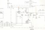
The power to the unit should be as shown below, "C" should have +24 vdc with respect to "A", which is ground.
There are always errors in these diagrams, so study them carefully before deciding that something is wrong.
 

Attachments

jeffhuey1n

SMSgt, USAF (Ret.)
Steel Soldiers Supporter
1,890
1,480
113
Location
Laramie County, Wyoming
cranetruck, Boatcarpenter, thanks for the help. The system was sold as a functioning set up, which leads me to believe it's a power issue. What I can gather from the schematic, C is power, not A. Might have to rethink this radio thing. Engines, easy, transmissions, axles, not a problem. Electrons confuddle the daylights out of me....:???:
 

poof

Dirty Hippie
568
19
18
Location
Wisconsin, Watertown
if i look at it correctly... the B ---C--D-- wires all get power and A is the only ground...
and this would go to the mount that holds the RT-524 in it first... then out of that to other Radio/commo
Yes?
 

Armada

New member
3,046
4
0
Location
Buick City, MI
I know you said it was sold as a "verified" working unit, but check to see if the am-1780 has internals. I had a similar experience a few years back. I had installed all new components and I still couldn't get the vic-1 to function. Bjorn (Cranetruck) helped me alot with my install back then too. He literally wrote the book, or article rather, on mounting, connecting, diagnosing, the vic-1. We were stumped.
Come to find out the am-1780 was missing the majority of it's internal components! And this was a "new in the box, never been used, never been opened, still sealed in its bag when produced at the factory", amp. Must have been built on a Friday. Apparently they do not function test them 100% after being produced. Anyway, got a new one and it all worked perfect. Good luck.
 

jeffhuey1n

SMSgt, USAF (Ret.)
Steel Soldiers Supporter
1,890
1,480
113
Location
Laramie County, Wyoming
Thanks everyone! The internals are all in the 1780. Looking at the schematic, it looks like A is supposed to be ground, B is power and c and D aren't shown (TM 11-5830-340-30, FO-2 on page FP-3). This makes sense to me since it should only be a power and ground set up (at least to my confuddled mind). I'll give it a try and let you know.
 
Top
AdBlock Detected

We get it, advertisements are annoying!

Sure, ad-blocking software does a great job at blocking ads, but it also blocks useful features of our website like our supporting vendors. Their ads help keep Steel Soldiers going. Please consider disabling your ad blockers for the site. Thanks!

I've Disabled AdBlock
No Thanks