• Steel Soldiers now has a few new forums, read more about it at: New Munitions Forums!

  • Microsoft MSN, Live, Hotmail, Outlook email users may not be receiving emails. We are working to resolve this issue. Please add support@steelsoldiers.com to your trusted contacts.


Voltmeter in Yellow

usmcpatriot

Member
199
14
18
Location
Bumpass, VA
After having the pleasure of not having too many issues with my M 1008 over the years, well that's over. Hopefully any you all can help. ok, here goes. Starting procedure is simple, turn key, GP light comes on, push manual GP button, till GP light goes off, push starter button, starter turns starts engine....all this time voltmeter is in yellow...engine starts...after a couple of seconds, I hear a loud ratching sound from under dash, after the sound, voltmeter goes into green slightly and I'm off....So, my problem is probably something to simple, remember just a grunt, colorblind at that....The only difference is I don't hear that sound, the ratching sound and my voltmeter stay in the yellow.....Checked both batteries, checked both Alts, cleaned all terminals....Checking TMs now for troubleshooting....thanks any help will greatly appreciated....
 

Mg84648

Member
201
6
18
Location
Cumming, Ga
It sounds like your GP card might be trying to function properly but your GP relay is faulty. The 30 seconds after engine start with the needle down in the yellow is your after glow function controlled by your card if IRC. It will jump back up to green after 30 seconds or so.
 

cucvrus

Well-known member
11,263
9,552
113
Location
Jonestown Pennsylvania
turn key, GP light comes on, push manual GP button,
No reply cause I never had to turn the key and push a button. The TM's will not help if you have to push a button. Would help if I could but it is hard to tell from afar what kind of cobbling has gone on to the wiring harness. 1 wire changed makes the TM's useless. Good Luck.
 

usmcpatriot

Member
199
14
18
Location
Bumpass, VA
I changed the steering wheel way back when. So now I have to turn key to start. Guess that powers the system. Then just what I have been doing, so it worked that way, why change anything, I guess. The button I'm referring to is the manual glow plugs "button", if that helps? Thanks man.
 

MarcusOReallyus

Well-known member
4,524
808
113
Location
Virginia
The button I'm referring to is the manual glow plugs "button", if that helps?
The problem is that there is no glow plug button in the stock truck. That's an add-on, usually done to get around a failed GP controller card.

You also mentioned a start button, which, again, is not present on the stock truck.


Take a look at the Helpful Threads sticky at the top of the forum. There's a very good thread in there on the GP system. Might help.

BTW, new GP controller cards can be purchased from one of our members. Check the classified ad section.
 

Drock

New member
1,020
9
0
Location
Eatonton GA
Hey usmcpatriot I'm responding to your PM here. I think mg84648 as well as the others pretty much summed it up. It sounds like the glow plug card is trying to work but the GP relay is acting up. Frankly it sounds like you have a lot of wiring debauchery that needs to be put back to stock. As MarcusOReallyus mentioned there's a member on here that makes upgraded GP cards. I'd purchase one of those, and a new GP relay and just go back to stock. However leave the dog head relay.2cents
 

MarcusOReallyus

Well-known member
4,524
808
113
Location
Virginia
Hey usmcpatriot I'm responding to your PM here. I think mg84648 as well as the others pretty much summed it up. It sounds like the glow plug card is trying to work but the GP relay is acting up.
Possible, but there is another possibility. His GP card is lighting the WAIT light correctly, so his might have failed in the same way that mine did. Mine burned up the trace that handles the grounding of the GP relay, so the relay was not engaging. Everything else on the card was working.

usmc, try this: First, find your GP relay (if you haven't already). If it's a stock relay, you have 4 terminals, which are (top to bottom):


  1. Input from the battery (through the resistor, if you have not bypassed it). Fat red wire.
  2. Ignition input (smallish yellow wire, I think. Or maybe orange. Going from memory here.)
  3. Controller card input (or manual button, if it's been hacked). Smallish blue wire.
  4. Output to GPs (fat red wires)


Check the voltage at all 4 terminals. With the key OFF it should look like this:


  • 24/12v (depending on whether you have done the resistor bypass)
  • Zero
  • Zero
  • Zero

When everything is working correctly in a stock system, with the key ON it should look like this:


  • 12v (you should NOT see 24v even if you have NOT done the resistor bypass)
  • 12v
  • Zero
  • 12v


I suspect for your truck what you will see is this (not using the push button):


  • 24/12v (depending on whether you have done the resistor bypass)
  • 12v
  • 12v
  • Zero


Now, again, for your truck, let's try using the push button.

With the key ON and the manual GP button pushed it should look like this:


  • 12v (you should NOT see 24v even if you have NOT done the resistor bypass)
  • 12v
  • Zero
  • 12v


Try that and let us know the results, will you? And while you are poking around, try another test. Get a jumper of some kind. Alligator clips are great if you don't have a helper. Once you have verified the above, take another set of measurements, but this time connect a jumper from the #3 terminal (blue wire) to a good ground somewhere. When you have done that, with the key ON, you should hear the relay clunk as soon as you connect the jumper, and the voltages should be:


  • 12v (you should NOT see 24v even if you have NOT done the resistor bypass)
  • 12v
  • Zero
  • 12v

Let us know what you find.
 

usmcpatriot

Member
199
14
18
Location
Bumpass, VA
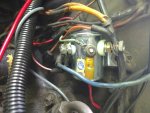
IMG_20180527_122419543.jpgIMG_20180527_122949701.jpg
Ok, checked the truck today, and as per MarcusOreallyus, the situation in the diagram:

I suspect for your truck what you will see is this (not using the push button):


  • 24/12v (depending on whether you have done the resistor bypass) 12.07 volts
  • 12v 11.29 volts
  • 12v 11.29 volts
  • Zero 0 volts

Is what I got added picture of new ECH ST 85, same scenario, volt meter still in the yellow, have to contact Xenocath SS member who helped with Mods.....thanks again brother
 

MarcusOReallyus

Well-known member
4,524
808
113
Location
Virginia
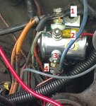
Let's look at this numbered diagram for reference, so we know which terminal we're talking about.

Relay is wired incorrectly.jpg

Help me understand how this thing is wired, because it's ...not stock. Here's what I think I see on each terminal:


  1. Several wires, two of which appear to be your GPs connections. Do I see others?
  2. A light blue wire and a red wire. (That ain't right!)
  3. Nothing. (That ain't right!)
  4. A fat blue wire (where does this go?)

Tell me if I'm seeing things correctly, please. Correct any mistakes I've made and fill in anything I've missed. Like, where does that small red wire on #2 go, and where does the fat blue wire on $3 go?


BTW, here's what it should be:

  1. Main power feed from resistor or battery
  2. Small red wire (supplies 12v when ignition is ON)
  3. Small, light blue wire (provides ground from controller card or manual switch)
  4. Two large orange wires (12v to your GPs from relay)
 

xenocath

searching.............
193
4
18
Location
Glen allen, VA
usmcpatriot
remove the glow plug card, operate system as you always have, report back or bring it by the house and i'll take a look at it. I had a similar issue when my card went. I removed card and all was fine, since you have a manual glow plug push button, the only thing you will lose is the wait light function.
 

MarcusOReallyus

Well-known member
4,524
808
113
Location
Virginia
The last thing he needs to do right now is to start pulling parts off and making more changes. He needs to understand where things are right now, and THEN figure out the next thing to do.
 

xenocath

searching.............
193
4
18
Location
Glen allen, VA
the way it is wired has been working for a long time. it is now acting exactly like the card has failed and is not operating the relay as it used to so maybe something burnt on card circuitry or crossed up frankly the cards are the weak link in that system. if it is crossed up somewhere removing the card will allow him to operate system safely using his manual glow button and let us see if that clears the issue with the charging system. pop out the card for testing purposes it can always be replaced if found to be bad. I have worked on his truck before so I was only attempting to help him based on what I know of the truck.
 
Last edited:

MarcusOReallyus

Well-known member
4,524
808
113
Location
Virginia
Yes, electrical is definitely not everybody's happy place, and electrical takes time! No sweat, we can help you work through it step by step. Can you confirm that the wiring is the way I think I see it in the pics above? Post # 12.
 
Top
AdBlock Detected

We get it, advertisements are annoying!

Sure, ad-blocking software does a great job at blocking ads, but it also blocks useful features of our website like our supporting vendors. Their ads help keep Steel Soldiers going. Please consider disabling your ad blockers for the site. Thanks!

I've Disabled AdBlock
No Thanks