• Steel Soldiers now has a few new forums, read more about it at: New Munitions Forums!

  • Microsoft MSN, Live, Hotmail, Outlook email users may not be receiving emails. We are working to resolve this issue. Please add support@steelsoldiers.com to your trusted contacts.

Weird Vacuum pump with tach sensor help?

2INSANE

Well-known member
725
825
93
Location
Belgrade, Montana
I was searching the web and found a few images of a 6.2 diesel vacuum pump with a tach speed sensor.

Is this a part that can be ordered or is it custom modified?

My goal is too hook up my tachometer to a better signal but yet still keep the vacuum pump in the same location.
 

Attachments

Barrman

Well-known member
5,273
1,793
113
Location
Giddings, Texas
I have not seen that part before. I know the tach signal sender without the vacuum pump is very expensive from GM. I had one that leaked oil the first time I fired up the engine. I went with the Dakota Digital alternator signal converter on my M715 which I have a complete CUCV dual alternator set up in.

Since you are going serpentine belt on your engine. I would suggest you also go the Dakota Digital route since the CS130, CS144, DS130 and AD244 alternators all have the tach signal built into them. I just swapped from a CS130 to a AD244 alternator on my Cowdog 6.5 truck. Much, much better charging experience. Since it is a different size than the CS130. My tach was off. I used the super easy adjustment buttons on the Dakota Digital device to adjust it back to right on again.
 

2INSANE

Well-known member
725
825
93
Location
Belgrade, Montana
I have not seen that part before. I know the tach signal sender without the vacuum pump is very expensive from GM. I had one that leaked oil the first time I fired up the engine. I went with the Dakota Digital alternator signal converter on my M715 which I have a complete CUCV dual alternator set up in.

Since you are going serpentine belt on your engine. I would suggest you also go the Dakota Digital route since the CS130, CS144, DS130 and AD244 alternators all have the tach signal built into them. I just swapped from a CS130 to a AD244 alternator on my Cowdog 6.5 truck. Much, much better charging experience. Since it is a different size than the CS130. My tach was off. I used the super easy adjustment buttons on the Dakota Digital device to adjust it back to right on again.
I’m guessing it is a custom made or modified part. It would be interesting to see a write up on how to build these. I am guessing the company is no longer in business.

I plan on keeping the V-Belt set up.
 

Keith_J

Well-known member
3,657
1,323
113
Location
Schertz TX
GM part for California vehicles. There is a chapter in the book "The 6.2L Diesel Engine" published by the Diesel Page . Dr Lee Swanger wrote the chapter.
This engine speed sensor on top of the vacuum pump generates a variable frequency alternating current. The circuit diagram first converts this to a sawtooth wave form with the capcitor, then uses the resistors as a voltage ladder and the transistor gate is now a comparator. This turns the sawtooth into an equivalent pulsed direct current waveform, the kind of signal most tachometers use.

This vacuum pump is as rare as hen's teeth. Best to go with Barrman's solution and use the Dakota Digital signal conditioner off the alternator frequency tap.

Or get a VDO tachometer for 100 dollars that works from the alternator tap.
 

Keith_J

Well-known member
3,657
1,323
113
Location
Schertz TX
It is probably speed sensor, not tach. Atleast that i find in the interweb...
What is the difference? Tachometer is an engine speed sensor. Most aftermarket or speed shop tachometer work off a square wave signal as that is what was common on breaker point ignition.

The pictured part uses a rotating magnet to induce alternating current output with a frequency proportional to engine speed. This is much better from an electrical standpoint since there are no points to wear out and the sine wave induces less radio frequency noise...

This part was only on California 6.2 diesels to drive the EGR system. Later diesels with electronic transmissions used the ESS only drive, no vacuum pump.
 

Keith_J

Well-known member
3,657
1,323
113
Location
Schertz TX
If your goal is a better signal, what is bad about the alternator tap? Belt drive? The Dakota Digital interface has great range of calibration. Since the alternator is spinning much faster than the crank, the sampling frequency is much higher than say a gear tooth Hall Effect sensor on the cam/IP gear. 27SI alternators are 16 pole and in the CUCV, spin 2.58 times crank speed.

This antiquated ESS spins at half crank speed with only 8 poles.

My 1031 came with a Hall Effect speed sensor , mounted on the Spicer PTO, for the 12 kW generator in the back. This was necessary because the slippage in the torque converter would make the governor hunt and output frequency would be unstable.
 

2INSANE

Well-known member
725
825
93
Location
Belgrade, Montana
If your goal is a better signal, what is bad about the alternator tap? Belt drive? The Dakota Digital interface has great range of calibration. Since the alternator is spinning much faster than the crank, the sampling frequency is much higher than say a gear tooth Hall Effect sensor on the cam/IP gear. 27SI alternators are 16 pole and in the CUCV, spin 2.58 times crank speed.

This antiquated ESS spins at half crank speed with only 8 poles.

My 1031 came with a Hall Effect speed sensor , mounted on the Spicer PTO, for the 12 kW generator in the back. This was necessary because the slippage in the torque converter would make the governor hunt and output frequency would be unstable.
My problem is... I already have a Phantom 2 Tach gauge that is adjustable and it is already wired to the passenger alternator which shows 4000 rpm at idle. So I am looking for better signals.
 

Mullaney

Well-known member
Steel Soldiers Supporter
Supporting Vendor
7,767
19,872
113
Location
Charlotte NC
My problem is... I already have a Phantom 2 Tach gauge that is adjustable and it is already wired to the passenger alternator which shows 4000 rpm at idle. So I am looking for better signals.
.
Silly question... Any chance that there are DIP Switches on the Tach that you could change? Even though it isn't right, snap a picture of how it was. Then power down the truck, change one switch, power up - and see what happens. If it gets worse, put it back like it was, then start on the other end of the DIP Switch bank.

Maybe there is an instruction manual for the Tach?

Just guessing and hoping with you that it might work... I poked around. Seems like an AutoMeter gauge. Just a quick search didn't pull up any instructions. :-(
 

Valor

Active member
196
216
43
Location
Apple Valley, Ca.
I was searching the web and found a few images of a 6.2 diesel vacuum pump with a tach speed sensor.

Is this a part that can be ordered or is it custom modified?

My goal is too hook up my tachometer to a better signal but yet still keep the vacuum pump in the same location.
I have one of those vacuum pump/ess units in my 84 civy suburban with a 6.5 replant. It is a stock calif. vehicle. I've wanted to hook the ess to a tach but having trouble figuring out the wiring. I have seen the info from Lee Wagner. If I were you, I would go with the alternator tach setup. Good luck.
 

Valor

Active member
196
216
43
Location
Apple Valley, Ca.
GM part for California vehicles. There is a chapter in the book "The 6.2L Diesel Engine" published by the Diesel Page . Dr Lee Swanger wrote the chapter.
This engine speed sensor on top of the vacuum pump generates a variable frequency alternating current. The circuit diagram first converts this to a sawtooth wave form with the capcitor, then uses the resistors as a voltage ladder and the transistor gate is now a comparator. This turns the sawtooth into an equivalent pulsed direct current waveform, the kind of signal most tachometers use.

This vacuum pump is as rare as hen's teeth. Best to go with Barrman's solution and use the Dakota Digital signal conditioner off the alternator frequency tap.

Or get a VDO tachometer for 100 dollars that works from the alternator tap.
Keith_J thank you for the explanation of how that circuit works. Not sure what a comparator is though. I'll keep investigating and see if I can drive a tach with that circuit and my vacuum pump/ess unit. Could I ask you more about that circuit from Lee Wagner?
 

Keith_J

Well-known member
3,657
1,323
113
Location
Schertz TX
The ESS signal is an alternating current sine wave, frequency dependent on engine speed. This circuit first changes this sine wave to a sawtooth wave using the capacitor. This is then compared to the steady state 13 volt direct current using the two resistors. When this voltage crosses zero, it causes the transistor to shut off. When voltage rises and crosses zero again, the transistor turns on and conducts.
This transforms the sawtooth to a square wave, an input that mimics the required signal for a typical spark engine tachometer
 

Keith_J

Well-known member
3,657
1,323
113
Location
Schertz TX
To further the circuit explanation, the sawtooth wave varies from V+ to V- with a frequency dependent on engine speed. There are points in time where it crosses zero volts and then becomes negative.

The resistor pair, 220 and 15 k ohm resistors are in series with the 13 volt DC input. When the sawtooth wave is at its maximum positive voltage, the voltage at point B is 13 volts, causing the transistor to conduct, in doing so, the voltage at point C is now zero.
When the sawtooth wave is on a zero crossing, voltage at point B is 13 minus the 15k, 220 ohm voltage divider.
When the sawtooth waveform is at its negative maximum, the voltage goes to some negative value, cannot calculate as magnitude of the sawtooth is not given. This causes the transistor to be open, making the voltage at point C to be 13.

The resistor values change the duty cycle of the output square wave form, in the sense of a breaker point system, this would be dwell. Most tachometers are not sensitive to this value.
 

Valor

Active member
196
216
43
Location
Apple Valley, Ca.
To further the circuit explanation, the sawtooth wave varies from V+ to V- with a frequency dependent on engine speed. There are points in time where it crosses zero volts and then becomes negative.

The resistor pair, 220 and 15 k ohm resistors are in series with the 13 volt DC input. When the sawtooth wave is at its maximum positive voltage, the voltage at point B is 13 volts, causing the transistor to conduct, in doing so, the voltage at point C is now zero.
When the sawtooth wave is on a zero crossing, voltage at point B is 13 minus the 15k, 220 ohm voltage divider.
When the sawtooth waveform is at its negative maximum, the voltage goes to some negative value, cannot calculate as magnitude of the sawtooth is not given. This causes the transistor to be open, making the voltage at point C to be 13.

The resistor values change the duty cycle of the output square wave form, in the sense of a breaker point system, this would be dwell. Most tachometers are not sensitive to this value.
The diagram I have doesn't show point B or C. Not sure what they refer to. My ess has 2 pins for a connector. In the diagram I have it only shows one lead from the ess going into the circuit. What happened to the other? Do the pins have polarity? I have the Diesel Page book that has the article that Lee Swanger wrote about this circuit. It leaves me with lots of questions. My civy 6.5 doesn't have an ecm. I don't know why it came with the ess. Where would I connect an oscilloscope to that circuit and which probe goes where? Does one lead from the ess have to be grounded to chassie? Sorry for all the questions. I am just confused. Thanks for your explanations.
 

Attachments

Keith_J

Well-known member
3,657
1,323
113
Location
Schertz TX
The ESS generates a low voltage alternating current, one pin goes to ground, the other is the input to this circuit. Doesn't matter which, this is alternating current so they interchange.

The transistor has 3 connections, B, C and E. Base, collector and emitter. They are labeled on the diagram.
 

Valor

Active member
196
216
43
Location
Apple Valley, Ca.
The ESS generates a low voltage alternating current, one pin goes to ground, the other is the input to this circuit. Doesn't matter which, this is alternating current so they interchange.

The transistor has 3 connections, B, C and E. Base, collector and emitter. They are labeled on the diagram.
After I posted to you the other day, I thought about the B and C points and remembered about the Base, Collector, and Emitter of the transistors and it made sense. If I wanted to hook up an oscilloscope to this circuit and see the waveforms, would I put the negative probe to ground and the positive probe to point B or C? I am trying to hook this up a HUMVEE tach. Thanks for your help.
 

Attachments

Keith_J

Well-known member
3,657
1,323
113
Location
Schertz TX
After I posted to you the other day, I thought about the B and C points and remembered about the Base, Collector, and Emitter of the transistors and it made sense. If I wanted to hook up an oscilloscope to this circuit and see the waveforms, would I put the negative probe to ground and the positive probe to point B or C? I am trying to hook this up a HUMVEE tach. Thanks for your help.
C. When the transistor is on, collector voltage goes to ground. When off, the voltage is to the rail, through the 1k ohm resistor. This resistor value is based on the impedance of the tachometer.
 

Sharecropper

Well-known member
Steel Soldiers Supporter
1,836
989
113
Location
Paris KY
After I posted to you the other day, I thought about the B and C points and remembered about the Base, Collector, and Emitter of the transistors and it made sense. If I wanted to hook up an oscilloscope to this circuit and see the waveforms, would I put the negative probe to ground and the positive probe to point B or C? I am trying to hook this up a HUMVEE tach. Thanks for your help.

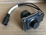
That is the same tach that I plan to use in my new gauge panel. Because I am swapping the TH400 for a 700R4, I won't need the vacuum pump anymore, so I installed a HMMWV oil pump drive with tach sender on top. It seems pretty simple to hook up, 24v in and 24v to ground, with the 2-wire signal from the sender going to the other 2 posts. Are you planning on keeping the TH400 transmission which requires vacuum?

HMMWV tach signal sender with female-side plug.JPG
 
Top
AdBlock Detected

We get it, advertisements are annoying!

Sure, ad-blocking software does a great job at blocking ads, but it also blocks useful features of our website like our supporting vendors. Their ads help keep Steel Soldiers going. Please consider disabling your ad blockers for the site. Thanks!

I've Disabled AdBlock
No Thanks