• Steel Soldiers now has a few new forums, read more about it at: New Munitions Forums!

  • Microsoft MSN, Live, Hotmail, Outlook email users may not be receiving emails. We are working to resolve this issue. Please add support@steelsoldiers.com to your trusted contacts.

What have you done to your CUCV today/lately - Part 2

german m1008

Well-known member
Steel Soldiers Supporter
888
1,321
93
Location
Rhein-Main Area, Germany
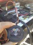
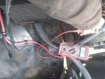
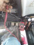
Grounded the pink fuel tank lead with the ignition on and the gauge read empty, which confirms the bad sending unit. Decided to look into the non working votlmeter while I was doing electrical work today. Took the voltmeter out and hooked it to the battery with some alligator clips and got no needle movement so I'll be getting a new one soon.View attachment 787233

....... you connected the 24V voltmeter to one battery (12V)........ that cannot work
 

emeralcove

Member
Steel Soldiers Supporter
134
15
18
Location
Battle Ground/WA
Crossover steering requires at least 2 inches of lift, other wise there is interference with the frame and engine crossmembers.

Sent from my SM-S920L using Tapatalk
Thank you, I have been looking at that conversion but thought I saw where some lift was required but then couldn't find the info again.
 

cucvrus

Well-known member
11,473
10,434
113
Location
Jonestown Pennsylvania
Been getting some more work done on the M1010. Finished up the Paradox kit. Got some adapters to use my new water temp sender and the crossover bypass port to the water pump. Because the angle of the Humvee bypass port is different than the stock crossover, I found I needed to use a molded 45* hose. Also swapping the harmonic balancer to a Fluidampr unit, I got the old one removed. Glad I did since the rubber ring has split and is just starting to work its way out. Waiting on an installer that has the 16x1.5mm crank adapter to show up. Also swapped out the glow plug relay.

View attachment 787224

View attachment 787225

View attachment 787226

View attachment 787227

View attachment 787228

View attachment 787229

View attachment 787231

View attachment 787232

View attachment 787230
I hope you are going to put a new front main seal in while you have that balancer off. where is the rubber falling out of the balancer? Asking because I never seen one go bad on a CUCV. Good Luck. Be Safe. Maybe I am NOT looking at the right place. And the machine shop told me they would sell me one but I don't need one.
 

chevymike

Well-known member
597
463
63
Location
San Diego, CA
I hope you are going to put a new front main seal in while you have that balancer off. where is the rubber falling out of the balancer? Asking because I never seen one go bad on a CUCV. Good Luck. Be Safe. Maybe I am NOT looking at the right place. And the machine shop told me they would sell me one but I don't need one.
Yes sir, I am replacing that seal. Yeah, this isn't the first time I have had balancers go bad. Very common on older SBC engines. You can see on the back side where the rubber started to split and is just starting to poke out from the edge, this is the start and will only get progressively worse.

0105201128_HDR.jpg
 

cucvrus

Well-known member
11,473
10,434
113
Location
Jonestown Pennsylvania

chevymike

Well-known member
597
463
63
Location
San Diego, CA
Drill out those Mud Dauber nests. They are making it off balance. Them little wasps can bring down a plane. https://www.theregister.co.uk/2016/05/06/wasps_force_two_passenger_jets_into_emergency_landings/
I had a balancer on a 6.2 that was solid mud and vibrated badly. The entire balancer was encrusted in mud and grass. It chewed the front seal out. I was the guy that done it. I picked up the grass in the field and the mud in the swamp out back.
Those are not affecting the rubber ring being split. It is getting replaced with my Fluidampr that I already have for it.
 

Sharecropper

Well-known member
Steel Soldiers Supporter
1,836
987
113
Location
Paris KY
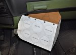
Built a mock-up of my new gauge cluster for my M1028. Everything fit as designed, so actual metal fabrication will start next. All gauges will be mechanical - Oil Pressure, Water Temperature, Transmission Temperature, Fuel Pressure, and Oil Temperature. In the middle will be a brand new HMMWV 3500 rpm Tachometer. The factory pop-down ashtray and housing will be removed and all wiring and thermocouples will traverse from the rear of the gauge cluster through the hole where the ashtray was. I am going to do away with the OEM transfer case shifter/linkage and replace it with a custom cable shifter mounted on the driver's side of the tunnel closer and more convenient. The cable shifter will operate the new NP241 transfer case I just ordered from Mark Bendler at Kodiak Trucks. The flat space on top of the gauge cluster will be where my iPhone holder will go. USB ports and switches for the heated seats will be on the side facing the passenger seat.

DSC_0751 (2).JPG
 

83k30

Member
63
38
18
Location
Jax, Fl
....... you connected the 24V voltmeter to one battery (12V)........ that cannot work
I was under the impression that the voltmeter was a 12v unit that used the 300ohm resistor to cut the 24v feed down to 12v. Tried it with both the resistor on and off the meter. But your post made me curious so I tried it hooked to the 2nd battery and it worked! Learned something new. I am surprised the 12v feed didn't move the needle though...IMG_20200107_132511907.jpg
 

83k30

Member
63
38
18
Location
Jax, Fl
Did you check the 10 amp fuse in the bottom of the fuse box? That is the voltmeter fuse. Check back. The gauge looks great. Good Luck.
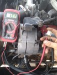
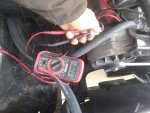
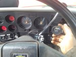
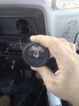
So I have some interesting results from my checks. 10 amp fuse checked out good. The voltmeter works when isolated from the factory plug and shows both alternators to be charging correctly. Pulled the two pin plug from each alternator to check for battery voltage there. Gen 1 showed 13.1V at the plug. Gen 2 showed 0.0V at the plug except when I grounded to the battery, then it showed 26.1V. Went back and checked the voltage at the plug for the voltmeter and had the same results; 0 volts when using the plug but correct voltage when grounded to the dash...IMG_20200108_122743642.jpgIMG_20200108_122523986.jpgIMG_20200108_122547004.jpgIMG_20200108_123036354.jpgIMG_20200108_123223256.jpg
 

cucvrus

Well-known member
11,473
10,434
113
Location
Jonestown Pennsylvania
You do have issues. You must have a Gen2 idiot light that works for that alternator to charge. I don't think that is what is causing the voltmeter to not work. It would show a low charge. Hard to tell what has been cut into. I see things that are not original and don't know what else has been changed. Good Luck.
 

cucvrus

Well-known member
11,473
10,434
113
Location
Jonestown Pennsylvania
I was under the impression that the voltmeter was a 12v unit that used the 300ohm resistor to cut the 24v feed down to 12v. Tried it with both the resistor on and off the meter. But your post made me curious so I tried it hooked to the 2nd battery and it worked! Learned something new. I am surprised the 12v feed didn't move the needle though...View attachment 787365
Is this gauge reading with the engine running?
 

83k30

Member
63
38
18
Location
Jax, Fl
Is this gauge reading with the engine running?
Yes. I tried another test to confirm my suspicion with the grounding issue at both the gen2 alternator and voltmeter circuit. I plugged the voltmeter into the factory harness and this time added a temp/trial ground via some alligator clips. Voltmeter worked correctly and showed both alternators to be charging. I am going to study some more diagrams to see where the gen 2 and voltmeter circuits ground. I replaced the under dash realys just to be sure but that did not cure the grounding issue. Will post more as I dig into it.IMG_20200108_154715829.jpg
 

dougco1

Well-known member
Steel Soldiers Supporter
867
647
93
Location
Cooperstown NY
Yes. I tried another test to confirm my suspicion with the grounding issue at both the gen2 alternator and voltmeter circuit. I plugged the voltmeter into the factory harness and this time added a temp/trial ground via some alligator clips. Voltmeter worked correctly and showed both alternators to be charging. I am going to study some more diagrams to see where the gen 2 and voltmeter circuits ground. I replaced the under dash realys just to be sure but that did not cure the grounding issue. Will post more as I dig into it.View attachment 787538
I thought the volt meters only got their grounding through the steel mounting bracket to the back side of the dash plate.
 

chevymike

Well-known member
597
463
63
Location
San Diego, CA
I thought the volt meters only got their grounding through the steel mounting bracket to the back side of the dash plate.
I doubt it. All gauges I have ever worked with always had a ground connector as many times they are mounted in something non conductive (i.e. the dash cluster). I know on my last M1010 when I converted it all to 12v, I took the original gauge out, cut the two connectors off the old gauge wiring and hooked them to the positive and negative posts on the new gauge. Worked as expected.
 

SDJunkMan

Member
36
11
8
Location
Rapid City/SD
Finally got my starter back from the rebuilder and installed it. Fired right up. Been too cold to do much with the cobbled up wires to the starter, so I did a couple of temporary repairs and will do a better fix when it warms up.

Snowed last night so I was glad that I got it running again, went to plow and found a fried selenoid coil on the lift function. If it's not one thing it's another! Waiting on parts again.
 
Top
AdBlock Detected

We get it, advertisements are annoying!

Sure, ad-blocking software does a great job at blocking ads, but it also blocks useful features of our website like our supporting vendors. Their ads help keep Steel Soldiers going. Please consider disabling your ad blockers for the site. Thanks!

I've Disabled AdBlock
No Thanks