• Steel Soldiers now has a few new forums, read more about it at: New Munitions Forums!

  • Microsoft MSN, Live, Hotmail, Outlook email users may not be receiving emails. We are working to resolve this issue. Please add support@steelsoldiers.com to your trusted contacts.

Winch controller wiring questions on M998; three wires - black, white and green - need help

dace

New member
18
8
3
Location
Arizona
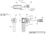
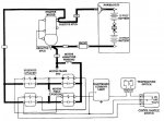
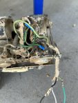
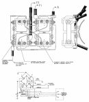
Anyone here a winch wiring expert? My 1986 M998 has a factory installed Warn 6,000lb winch. The controller was cut off at some point and I want to get it working again. I have a black wire, green wire and white wire coming from the winch control module on the winch. I would assume this is where the controller was once attached to. The white wire has 24v to it. Most of the Warn schematics I find show the white wire as power. When I jump the white wire to the black wire the winch appears to go in reverse. When I jump the green wire to the white wire nothing happens. Would this mean my next step is to check the solenoid the green wire is attached to? Or am I doing it wrong and need to have them all wired up to make it work in both directions.. I am assuming if I attached the three wires to a three way throw switch the same thing would happen if the green wire is broken. I.e. it only works in one direction.ai180.photobucket.com_albums_x231_Ridgerunnerras_Warn_20winch_2bca7aa18f9dcdf90783fdd41a5b58a7.pngai180.photobucket.com_albums_x231_Ridgerunnerras_Warn_20winch_20wiring_20diagrams_Remote_3_Wire.pngTM-9-2320-280-20-3_1076_2 winch wiring diagram.jpg
 

Mogman

Moderator
Staff member
Moderator
Steel Soldiers Supporter
6,083
8,515
113
Location
Papalote, TX
The pictorial does not match the schematic (third attachment), the pictorial shows the coils for the solenoids in parallel, the schematic shows them in series (12V coils)
If it is wired as in the picture make sure you have ground wires going to both the #1 and #4 solenoids second small terminals, if it is actually wired as in the schematic make sure one of the coils is not open..
I am assuming when you say nothing happens that means you are not even hearing a click of the solenoids.
 
Last edited:

Mogman

Moderator
Staff member
Moderator
Steel Soldiers Supporter
6,083
8,515
113
Location
Papalote, TX
There is also a thermal switch on the green line that could be bad.
 

dace

New member
18
8
3
Location
Arizona
The pictorial does not match the schematic (third attachment), the pictorial shows the coils for the solenoids in parallel, the schematic shows them in series (12V coils)
If it is wired as in the picture make sure you have ground wires going to both the #1 and #4 solenoids second small terminals, if it is actually wired as in the schematic make sure one of the coils is not open..
I am assuming when you say nothing happens that means you are not even hearing a click of the solenoids.
yeah not even a small click. Its just dead.
 

Mogman

Moderator
Staff member
Moderator
Steel Soldiers Supporter
6,083
8,515
113
Location
Papalote, TX
I would go ahead and wire up the switch, easier for testing than hooking up a jumper every time you test
 
Top
AdBlock Detected

We get it, advertisements are annoying!

Sure, ad-blocking software does a great job at blocking ads, but it also blocks useful features of our website like our supporting vendors. Their ads help keep Steel Soldiers going. Please consider disabling your ad blockers for the site. Thanks!

I've Disabled AdBlock
No Thanks