• Steel Soldiers now has a few new forums, read more about it at: New Munitions Forums!

  • Microsoft MSN, Live, Hotmail, Outlook email users may not be receiving emails. We are working to resolve this issue. Please add support@steelsoldiers.com to your trusted contacts.

Wiring Schematics for M1078 (1997 with new C7)?

spoonbender

New member
19
16
3
Location
WI
Received today - manufactured 1/24, so brand new.

Now a really dumb question - how do I install it? I can see the 2 plugs that go into it - no issue plugging them in, but I'm not seeing any airlines to connect (which I believe are connected?). Looking through the TM's, and not finding a procedure on it ... not a wear item apparently?!?

Can anyone give some pointers?

Thx!
 

GeneralDisorder

Well-known member
Steel Soldiers Supporter
2,076
5,308
113
Location
Portland, OR
Received today - manufactured 1/24, so brand new.

Now a really dumb question - how do I install it? I can see the 2 plugs that go into it - no issue plugging them in, but I'm not seeing any airlines to connect (which I believe are connected?). Looking through the TM's, and not finding a procedure on it ... not a wear item apparently?!?

Can anyone give some pointers?

Thx!
That truck wouldn't have the air lines because it didn't originally have the C7. The air lines to the MMDC are not part of the electrical harness so probably haven't yet been added. They originate from a T off the primary and secondary air brake supply lines going into the pedal valve. The T has a 1/4" line going to each of the MMDC pressure transducer ports. I highly recommend you install inline filters in these lines to prevent moisture and debris contamination of the sensors.

Also since you don't have the C7 truck's Bendix E-7 pedal valve you also don't have it's adapter bracket which is also (also) the mounting bracket for the MMDC. So you'll have to come up with your own mounting solution. Fun, Fun.
 

spoonbender

New member
19
16
3
Location
WI
That truck wouldn't have the air lines because it didn't originally have the C7. The air lines to the MMDC are not part of the electrical harness so probably haven't yet been added. They originate from a T off the primary and secondary air brake supply lines going into the pedal valve. The T has a 1/4" line going to each of the MMDC pressure transducer ports. I highly recommend you install inline filters in these lines to prevent moisture and debris contamination of the sensors.

Also since you don't have the C7 truck's Bendix E-7 pedal valve you also don't have it's adapter bracket which is also (also) the mounting bracket for the MMDC. So you'll have to come up with your own mounting solution. Fun, Fun.
Yep, what I was expecting. Think I'm going to try to fit it behind the dash, but will have to do some test fitting and see if running air lines up will work. Will also read up on the air system TM's, as I know there are plenty of leaks and a few brake lines to replace.

Good news is - believe the MMDC missing was stopping the 24v power from getting through (turned off right after the batteries?), so hopeful plugging this in will light up things a bit. But already found some wiring I need to troubleshoot (engine ECM), and will have to see if I have an ABS ECU - I have no idea where it is or what it looks like...

And more good news - the accelerator is updated to the new - found a throttle sensor on it, and plugged into the harness.

Still trying to figure out why they stopped on the overhaul - have a feeling I'll find out soon!


Thanks much!
 

spoonbender

New member
19
16
3
Location
WI
Another update from today - the MMDC is installed, but did not notice anything "lighting up", so I started tracing power from the batteries. Didn't take me long to find an issue - the voltage regulator (called LSDC in the specs) - the 24V and 12V lines from the battery to the LSDC are good to go, but the 'load' outputs - 24V measured 24V - the 12V line measured 24V. Appears something is not working correctly. This also means the 24V is going in the PDM where there should be 12V - luckily the K2 relay stopped it. I have a spare LSDC (in the pile of parts) - I'll try to test that one before I swap anything ... I suspect theres a reason they removed it though...

Another finding - I have ABS, so this is an A1 truck - very good news, as I suspect the CAN bus lines/etc are run, and should work. Also gives me hope the new transmission controller will work with the existing - still have to troubleshoot why I can't see anything on the diagnostic port, but suspect the power issue above may be a part of it.

Question for any electrical experts ... anyone know where CB60 is located? The schematics are showing this is the line from the voltage regulator to this 40A circuit breaker - and supplies power to the C7 ECU - but not in the dash 'boxes'. And not seeing the lines from the voltage regulator to the engine, so wondering if I need to add it...

Thanks for reading!
 

GeneralDisorder

Well-known member
Steel Soldiers Supporter
2,076
5,308
113
Location
Portland, OR
Not familiar with this "LSDC" - can you show this to me on the schematic? Are you sure you don't mean LBCD (Load Battery Control Device)? If so that's not a voltage regulator...... the dual voltages come from tapping the center of the battery bank for 12v and the full battery bank for 24v so if you have 24v where you should have 12v then either the battery connections are wrong or perhaps wires are connected to the LBCD improperly..... being an A0 truck you would have had a PPD (Polarity Protection Device) originally instead of the dual-purpose LBCD that was adapted later in the A1(R). Being you have what seems to be a complete A1R wiring harness you should have a cannon plug for the LBCD. The "voltage regulator" (the only one I'm aware of the truck having) is located on top of the alternator and regulates it's output in terms of charging voltage for both the 12v and 24v circuits.

Need a lot of clarification.
 

Ronmar

Well-known member
3,881
7,549
113
Location
Port angeles wa
what General said, i think you are referring to the LBCD, and it sounds like something is not connected correctly from the batteries. You should have 12 and 24 connected thru the manual disconnect, thru the remote disconnect relay then on to the 12 and 24v batt terminals on the LBCD. The alternator 12 and 24v cables are also connected here. The 12mand 24v load terminals on the LBCD have cables running to the PDP in the dash to the 12 and 24v batt terminals and K1 and K2 Which provide 12 and 24v ign when powered…

In answer to your question, CB60 shows that it is connected to the 24v load terminal on the LBCD. It shows the fuse connected with TL111 and 112. The first or second page in the A1R manual shows some of the TL locations on the chassis, TL111 is shown in close proximity to where the LBCD is located under/inboard of the spare tire…
 

spoonbender

New member
19
16
3
Location
WI
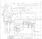
Suspect you are both correct and the name may change across versions (?) ... and I have the typo in there as well. Here's a snip from the schematics that I'm looking at - middle left, the LSCD. I'll run through the Niehoff diagnostic steps (found them after leaving yesterday), and see if it's still good. Just confusing how the 12V in (as measured) is coming out 24V. I'll have to verify the wiring and make sure no shorts. Fun fun indeed!
.1710164105864.png

And thanks for the tips Ronmar - I'll dig through the TM's for the locations, as yes, this is all by the spare tire / ABS controller area.

Thanks!
 

coachgeo

Well-known member
5,150
3,466
113
Location
North of Cincy OH
Suspect you are both correct and the name may change across versions (?) ... and I have the typo in there as well. Here's a snip from the schematics that I'm looking at - middle left, the LSCD. I'll run through the Niehoff diagnostic steps (found them after leaving yesterday), and see if it's still good. Just confusing how the 12V in (as measured) is coming out 24V. I'll have to verify the wiring and make sure no shorts. Fun fun indeed!
.View attachment 918826

And thanks for the tips Ronmar - I'll dig through the TM's for the locations, as yes, this is all by the spare tire / ABS controller area.

Thanks!
hmm.... going by nomenclature used as we know it:
LBCD = Load Balance Control Device

going by the schemeatic that seems to shows some sort of "sensing" purpose then you get
LSCD = Load SENSING Control Device. ???
 

coachgeo

Well-known member
5,150
3,466
113
Location
North of Cincy OH
Suspect you are both correct and the name may change across versions (?) ... and I have the typo in there as well. Here's a snip from the schematics that I'm looking at - middle left, the LSCD. I'll run through the Niehoff diagnostic steps (found them after leaving yesterday), and see if it's still good. Just confusing how the 12V in (as measured) is coming out 24V. I'll have to verify the wiring and make sure no shorts. Fun fun indeed!
.View attachment 918826

And thanks for the tips Ronmar - I'll dig through the TM's for the locations, as yes, this is all by the spare tire / ABS controller area.

Thanks!
one of the problems with the LBCD system is it does its magic by manipulating the relays (battery disconnects) located in the box attached to side of battery box. Well these are known to corrode, short out etc.

Since your LSCD-ish thingy seems to be wired in similar to the LBCD.... maybe also your short is there at those relays hence why you get 24v at 12v..... or Sgt. Snuffy bypassed relays by hooking wires together...... but hooked wrong ones together?
 

GeneralDisorder

Well-known member
Steel Soldiers Supporter
2,076
5,308
113
Location
Portland, OR
That's a typo in the schematic I assume. Or maybe it was an early acronym for Load Sensing/System(?) Control Device or some such. Either way it's the same part and now referred to as the Load Battery Control Device.

See the diodes inside it? Sounds to me like you have a 24v supply wired to the 12v OUT. Disconnect all the wires from the 12v OUT stud and retest the voltage there. If there is 12v on the IN stud then you should have 12v on the OUT stud with nothing connected to it. If you still have 24v on the 12v OUT stud with nothing connected - the LBCD has failed in strange and mysterious ways. Pitch it in the dumpster.
 
Last edited:

spoonbender

New member
19
16
3
Location
WI
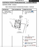
Searching the TM's, I found this for CB60, which confirmed my suspicion it's not in the boxes - but not much else (could only find the operator and technical manual TM's). From the picture, still not sure exactly where to look for it (or where to install it should I need to...). Suspect it's around the spare tire / coolant tank area:
1710289363895.png

and found something eerily similar here:


Thanks!
 

coachgeo

Well-known member
5,150
3,466
113
Location
North of Cincy OH

spoonbender

New member
19
16
3
Location
WI
I have the box - relays and all, but no CB60 or wires in the box,

Does anyone know if the A1R have the same circuit/wiring? Wondering if they ECU power is in the harness and not a direct circuit breaker connected line ... OR if this is part of the overhaul they just didn't get to yet.

Just seems odd if the ECU power is in the harness as they are not very big wires.
 
Top
AdBlock Detected

We get it, advertisements are annoying!

Sure, ad-blocking software does a great job at blocking ads, but it also blocks useful features of our website like our supporting vendors. Their ads help keep Steel Soldiers going. Please consider disabling your ad blockers for the site. Thanks!

I've Disabled AdBlock
No Thanks