• Steel Soldiers now has a few new forums, read more about it at: New Munitions Forums!

  • Microsoft MSN, Live, Hotmail, Outlook email users may not be receiving emails. We are working to resolve this issue. Please add support@steelsoldiers.com to your trusted contacts.

Yay I get to track down 24v gremlins - gauge issues, crank issues, K1 control, OP switch

Demoh

Member
217
26
18
Location
St Pete, FL
Ive been working on 1 particular unit for a little bit now after taking care of the engine side of things on an 803a. I can hear everybody now, yes I am running through the -24 and related docs. I normally wouldnt post if it wasnt some weird compound issue, or maybe my brain lacking direction / where to start on these complex issues.

Im hoping all of these problems are related in some way but staring at the schematics (btw, what happened to the high-res colored in the sticky? I had to find the CMEC layered one so the words are readable) until my head hurts I had to take a break.

Here is a list of the problems:
- No "pull" on L5 fuel solenoid. - ignore this, probably bad L5 or bad wire, deadcrank works so K2 is fine.
- Oil pressure gauge jumps from 60 to 80 when you turn panel lights on - sometimes erratic movement
- no coolant temp reading 90% of the time. When panel lights are on the coolant temp needle goes high erratically. Sometimes without panel lights coolant temp needle moves to high side (right)
- oil pressure switch theory of operation question - is the OP switch supposed to be NC when 0 psi and open when operating or vice versa? Either way in my troubleshooting I had to disconnect K20 and jump it in order to get power through K20 to K1 to close it, but I am thinking now that caused my issue with the OP switch because I tried to test it by disconnecting the OP switch to shut the unit down, it didnt shut down so I shorted the leads and it still didnt shut down. (In hindsight I think I just answered my question however I would still like to know the theory of operation from people smarter than me)
- both float switches are bad due to corrosion so its completely disconnected until I can get a replacement. (also theory of operation, magnets down = open, magnets up = closed, or does the float module invert the signals so down = closed and up = open, but after A9 its inverted?)


unit stopped cranking when moving S1 to start the starter engages for 1/6 of a rotation then quits. I may have caused this by swapping K20 with whatever is adjacent to it. Currently using deadcrank to start the unit. (im not sure on timing for when this problem started)

For the relays since I suspected a bad relay I ohmed the contacts. Knowing my meter is out of cal and shorting the leads shows about 5ohms, I found 1 NC contact on K20 which was reading about 10ohms. Because I couldnt confirm instrument error I swapped K20 with K19. I was still having issues after this which lead me to believe the relay was fine, so I proceeded to disconnect A and B from K20 and jump it with 24v manually so I could close K1. The whole reason I did this is because I needed to force the set to make power. (surprisingly, it does, S6 still needs to be cleaned though)

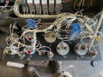
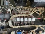
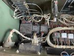
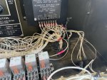
Unit has evidence of having the harness repaired. Its a pretty old Libby unit that looks like its been refreshed multiple times based on how many layers of CARC are on it and how rough everything is.

My next steps: use a different meter and replace the relays with known good / new relays. Test/Replace L5, (hoping for brilliant forum ideas at this point), then check wire for correct terminations and continuity.

Im thinking there is some wire issue with either gauges not getting enough juice causing erratic readings or a grounding issue.
 

Guyfang

Moderator
Staff member
Moderator
16,766
24,082
113
Location
Burgkunstadt, Germany
Ive been working on 1 particular unit for a little bit now after taking care of the engine side of things on an 803a. I can hear everybody now, yes I am running through the -24 and related docs. I normally wouldnt post if it wasnt some weird compound issue, or maybe my brain lacking direction / where to start on these complex issues.

Im hoping all of these problems are related in some way but staring at the schematics (btw, what happened to the high-res colored in the sticky? I had to find the CMEC layered one so the words are readable) until my head hurts I had to take a break.

Here is a list of the problems:
- No "pull" on L5 fuel solenoid. -(The K16 has to energize to get the pull function to work) ignore this, probably bad L5 (Well then test it. C is ground. Pull and Hold are hot.)


L5 Fuel Solenoid​
From​
Wire #​
P14-1​
RED​
Hold​
P14-2​
White​
Pull​
P14-3​
BLACK​
Ground​


1633377668333.png or bad wire, deadcrank works so K2 is fine.
- Oil pressure gauge jumps from 60 to 80 when you turn panel lights on - sometimes erratic movement (You need to check the proper positioning of every wire on the control panel, and then check grounds. Also look at where the wire harness moves. Places that may have broken a wire when the control panel has been opened and closed 10,000 times.)
- no coolant temp reading 90% of the time. When panel lights are on the coolant temp needle goes high erratically. Sometimes without panel lights coolant temp needle moves to high side (right)
- oil pressure switch theory of operation question - is the OP switch supposed to be NC when 0 psi and open when operating or vice versa? (Look at the schematic. Switches are always shown in the non powered position. NC.)


FL1 Low Fuel Level Float Switch​
From​
Wire #​
P12-3​
C​
N/C​
P12-4​
D​
Contacts​
FL2 Aux Fuel Pump Float Switch​
From​
Wire #​
P12-1​
A​
N/C​
P12-2​
B​
Contacts​


Either way in my troubleshooting I had to disconnect K20 and jump it in order to get power through K20 to K1 to close it, but I am thinking now that caused my issue with the OP switch because I tried to test it by disconnecting the OP switch to shut the unit down, it didnt shut down so I shorted the leads and it still didnt shut down. (In hindsight I think I just answered my question however I would still like to know the theory of operation from people smarter than me) You jumped K20. That makes the OP meaningless.
- both float switches are bad due to corrosion so its completely disconnected until I can get a replacement. (also theory of operation, magnets down = open, magnets up = closed, or does the float module invert the signals so down = closed and up = open, but after A9 its inverted?)

Test procedures are in the TM.
2-77-3. Testing FL-1 & FL-2.
a. Remove low fuel level/auxiliary fuel pump float switch, paragraph 2-77-2.
b. Position float switch in vertical position, similar to position as installed in fuel tank.
c. Set multimeter for ohms and connect positive lead to pin 2 and negative lead to pin 1 of electrical connector.
d. With upper float moving toward the down position, multimeter should indicate continuity 1/4 inch before float
reaches the down position.
e. Move upper float to the full up position, multimeter should indicate open circuit.
f. Disconnect multimeter leads from pins 1 and 2 and connect positive lead to pin 3 and negative lead to pin 4
of electrical connector.
g. Repeat steps d and e, except with lower float.
h. Replace low fuel level/auxiliary fuel pump float switch if indications are other than above.
i. Install low fuel level/auxiliary fuel pump float switch, paragraph 2-77-4.


unit stopped cranking when moving S1 to start the starter engages for 1/6 of a rotation then quits. (Test at S1-7, to see if you are losing 24 VDC while holding up S1) I may have caused this by swapping K20 with whatever is adjacent to it. Currently using deadcrank to start the unit. (im not sure on timing for when this problem started)

For the relays since I suspected a bad relay I ohmed the contacts.

2-33-2. Testing.

IAW the TM. Did you attach a 24 VDC source to the A&B contacts of the relay?

A. Release control panel by turning two fasteners and lower control panel slowly.
Remove applicable relay, paragraph 2-33-3.

B. Set multimeter for ohms and check for open circuits between terminals 7 and 4, 8 and 5, and 9 and 6. Check for closed circuits between terminals 7 and 1, 8 and 2, and 9 and 3.

C. Connect 24 VDC source to terminals A and B, and listen for audible actuation of relay. Set multimeter for ohms and check for open circuits between terminals 7 and 1, 8 and 2, and 9 and Check for closed circuits between terminals 7 and 4, 8 and 5, and 9 and 6.


If indications are other than above, relay is defective and must be replaced.
Install relay, paragraph 2-33-4.
Knowing my meter is out of cal and shorting the leads shows about 5ohms, I found 1 NC contact on K20 which was reading about 10ohms. (Ohms is a Lier. Two contacts can show ohms, and still not pass VDC.) To properly check if contacts are good, attach 24 VDC to the contacts and hook them up to a light, for instence. That way, if the light comes on, its good.) Because I couldnt confirm instrument error I swapped K20 with K19. I was still having issues after this which lead me to believe the relay was fine, so I proceeded to disconnect A and B from K20 and jump it with 24v manually so I could close K1. (If you did this, and it closed the K20 contacts, then K20 is good. The reason things do not work is because K20-A is not getting 24 VDC or K20-B is not hooked up to ground.) The whole reason I did this is because I needed to force the set to make power. (surprisingly, it does, S6 still needs to be cleaned though)

Unit has evidence of having the harness repaired. Its a pretty old Libby unit that looks like its been refreshed multiple times based on how many layers of CARC are on it and how rough everything is.

My next steps: use a different meter and replace the relays with known good / new relays. (Test them, and you will know whats good and bad.) Test/Replace L5, (hoping for brilliant forum ideas at this point), then check wire for correct terminations and continuity.

Im thinking there is some wire issue with either gauges not getting enough juice causing erratic readings or a grounding issue.

Take a good picture of the relays in the control cube and post it.
Open to read comments,
 

Demoh

Member
217
26
18
Location
St Pete, FL
Thanks for the direction. So I havent gotten far however I have made some progress.

Relays all test good using a halogen lamp. Also brought a different brand out of a known runner.

Chasing down the items Guyfang suggested I get some interesting results. Volt drop is more than I would expect for some solenoids / relays. At S7 I am getting 19v when holding Start. Part of this is my jumper cables to a pair of group31s, Ill bring a set of batteries tomorrow. All voltages at RUN are about 24v, only when holding Start do I get the drop.

The voltage drop is causing K16 to drop out which in-turn causes K2 to also drop.

Now, this is where things get interesting; at K16 A I get 18V or so. but at K16 B I get about 4-5V, giving me a net of 13V across the coil for K16.

So, Still thinking compound issues I think that fresh batteries physically installed are now necessary so I will repeat the testing tomorrow after that. Ill also bring a spare S14 because I think this one might not be functioning correctly. Disconnecting S14 and grounding K16B allows normal cranking.

In the bulkhead connectors theres some corrosion but not like ive seen before which has forced a repin. I may have 1 questionable pin which I will evaluate. (Kurt, did those pins come in?) Cleaned them up a bit while finding cuts on my hands.

I found some loose (a few full revolutions) nuts on K2 early on in the testing. Unfortunately that ended up not being the smoking gun.

Ill continue with the testing tomorrow as as it was mosquito-o-clock when I stopped.
 

Attachments

kloppk

Well-known member
Steel Soldiers Supporter
2,145
3,526
113
Location
Pepperell, Massachusetts
Yes, I have all the pins you requested.
Was waiting on the last damn part for the 60Hz controllers. Can ship the pins now if you want. Just let me know.
 

Demoh

Member
217
26
18
Location
St Pete, FL
Alright. its been a while but my initial hunch to 'put the batteries in and retest' was correct. Putting the batteries inside the gen instead of using my mobile 24v jump cart solved the starting issues.

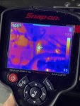
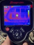
The generator overloaded after about 25 minutes at 10kw. Joy S8 time. I forgot to grab those pictures off my thermal imager but S8 was not happy, nor were some of the windings that were working harder than the rest. I wasnt satisfied with cleaning S8 up so I deleted it. Also put a temporary quad fuse in until I can find my holders.

After about an hour of running I found that the coolant gauge started slowly coming back to life. it still flickers with the OP gauge and panel lights so I have more gremlins to flush out but its getting there.

Since I have the S8 leads bolted together, has anybody had luck going to a terminal block with the leads?

Also, I havent amped the lines and they arent too hot in the pictures below, I suspect this is normal because the temps are only 105 or 111, but Ill be investigating these hotspots later on. Of course thats after I track down my gauge issues.

Oh and dead alternator, forgot to grab that picture also, looked like a block of ice connected to the engine on the thermal imager.

thumbnail_IMG_1746.jpg
thumbnail_IMG_1748.jpg
 

Demoh

Member
217
26
18
Location
St Pete, FL
Alternator exciter - bad pin
Coolant gauge - bad pin
coolant + oil + whatever else - bad ground. potential between the ground lug inside the cabinet and slave port is a whopping 4.5 volts.

Par for a '94 Libby that has evidence of many field repairs to the harness I suppose.
 
Top
AdBlock Detected

We get it, advertisements are annoying!

Sure, ad-blocking software does a great job at blocking ads, but it also blocks useful features of our website like our supporting vendors. Their ads help keep Steel Soldiers going. Please consider disabling your ad blockers for the site. Thanks!

I've Disabled AdBlock
No Thanks