Asmoday
Member
- 225
- 0
- 16
- Location
- Los Angeles, CA
OK...I have read as many of the posts as I can stand now on the GP 12v relay "bypass the resistor and connect to the firewall 12v source" mods... but I do thank all for their earlier informative posts.
My question is simple and I just want to confirm what I think is a typo in the TM schematics.
I want to keep the resistor and its original wiring intact so I plan on making a short lead with a fusible link, soldering, heat shrink etc.
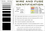
I looked at CUCV Electrics schematic as well as the TM schematics and understand the wire size legend. But in the schematics it says .8 for the SXL red primary wire and .3 for the blue fusible link.
Being that .8 equals 18ga and .3 does not exist in the TM legend...they must have meant to put 8 which is 8ga for the SXL primary lead and 3 for the fusible link which is 12ga.....correct? Being that I now have learned that a fusible link should be 4 sizes smaller than the primary wire it's spliced into.
I did notice on the M1010 schematic it appears to be correct.
Just double checking cause I go crazy over the little things...LOL.
Out of curiosity what is the actual amps draw by the GP relay through that 12v wire connected to the top post after the mod when the relay is energized and is a 8ga wire big enough for the short run to the 12v firewall source just above the relay?
Thanks!
 but I do thank all for their earlier informative posts.
My question is simple and I just want to confirm what I think is a typo in the TM schematics.
I want to keep the resistor and its original wiring intact so I plan on making a short lead with a fusible link, soldering, heat shrink etc.
I looked at CUCV Electrics schematic as well as the TM schematics and understand the wire size legend. But in the schematics it says .8 for the SXL red primary wire and .3 for the blue fusible link.
Being that .8 equals 18ga and .3 does not exist in the TM legend...they must have meant to put 8 which is 8ga for the SXL primary lead and 3 for the fusible link which is 12ga.....correct? Being that I now have learned that a fusible link should be 4 sizes smaller than the primary wire it's spliced into.
I did notice on the M1010 schematic it appears to be correct.
Just double checking cause I go crazy over the little things...LOL.
Out of curiosity what is the actual amps draw by the GP relay through that 12v wire connected to the top post after the mod when the relay is energized and is a 8ga wire big enough for the short run to the 12v firewall source just above the relay?
Thanks!
Last edited:


