• Steel Soldiers now has a few new forums, read more about it at: New Munitions Forums!

  • Microsoft MSN, Live, Hotmail, Outlook email users may not be receiving emails. We are working to resolve this issue. Please add support@steelsoldiers.com to your trusted contacts.

Air brake pressure gauge malfunction in LMTV

Klaus

New member
Steel Soldiers Supporter
17
21
3
Location
Maple Ridge / BC
I am scratching my head on this one - the air brake guages have stopped working.

I've got a first-gen M1078 A0 truck, mostly in excellent running order. Apart from needing to replace some rotten connectors on marker lights, it worked pretty well from when I received it from Memphis Eq. Been slowly been doing upgrades such as replacing the 3 lever light switch with the newer push-button unit (works great), new LED lights all round, other minor stuff like adding a back-up alarm and rear view camera.

So about the air brakes. The service and Park brakes apply and release as they should, but the for awhile the truck was having trouble building air after stepping on the brake pedal. I eventually found some kinked air lines at the rear cross member, another one at the left cab pivot point, one more on one of the front check valves under the cab at the driver's wheel well and yet one more under the dash at the Park Hand Valve. I also found that there was sometimes an air leak around the stem of the Park Valve handle, so I ordered one of the new combo Haldex controls from DP Equip. It took a bit of cussing and reading TM's to get the new unit installed, with new air lines to the floor fittings. Since I had Memphis upgrade the truck with an Air Con unit there was hardly any room for anything else under the dash, so that's how the air line got kinked I guess. All good fun.

Other stuff I've done on the air brake system:

- replaced 2-way check valve and old air lines on rear cross member
- replaced gladhand seals and filters, the dummy plugs were not sealing well
- rebuilt the unloader valves on the air compressor as one was gummed up and was probably why the truck refused to build air pressure after a heavy push on the brake pedal
- found some loose connections on Front and Rear stoplight switches, where the Park and Emerg indicator lights on the dash display would go off when they should be on
- confirmed no leak at Tractor Protection Valve, yet anyway. I hear they are notorious for venting air off once the diaphragms go bad. Along with the check valves

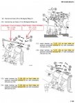
While I was under the dash replacing air lines and trying to figure out why I was not getting back up to 120 psi on the gauges, I noticed two air pressure transmitters / sending units that are conected to the front and rear air pressure gauges on the dash. Took the wires off the transmitters so I could read the TL markings. I then noticed that the transmitters were wired opposite to what is in the TM's. Okay... so I rewired them according to spec, see TM page below. All good right? Maybe not.

Air Transmitters.jpg


I tightened up the wires on the posts too much and stripped one. Not good. I ordered a replacement air pressure sender from Will at LMTVParts.com. He was extremely helpful in helping me identify where things might be going wrong. I now know more than before, a big thank-you goes out to Will... but there is still much I need to learn apparently!

Started truck up, air pressure gauges started at zero, then after a few minutes went hard over to maximum (above 120 psi) and stayed there, even if I stepped on the brake pedal. I put a voltmeter on the terminals with the Master Power switch on (but truck not running) and both transmitters are seeing -24 V (with the GND lead held on the G post on transmitters). CB76 was not popped on the breaker panel. Did not try swapping out any relays yet.

I thought, maybe the wires on the senders were right (the gauges worked before I started messing around) and if so, perhaps the wiring was backwards elsewhere. So I put the wiring on the senders back to non-TM mode (wires 150 and 156 switched, same with 151 and 157). Now the gauges read -12 V and were maxed out as soon as the Master Power was switched on. Started the truck up, let it run and it built air. After a few minutes, the needles suddenly dropped to about 65 psi and from then on they increased as air pressure built up to 120. Then the dryer purged and unloaded the compressor, as it should. I ran the truck up and down the driveway to test the brakes, they seemed fine. I then pumped the brake pedal to dump air and at 85 psi the front and rear stop indicator lights came on and the pressure gauges increased back to 120 psi as the compressor filled up the system.

But it does not seem right to have the gauges pegged high, then jump down and begin working normally. Also having the senders wired in reverse seems wrong. Nobody here where I live knows much about LMTV's, I've only seen one other rig like mine here and it was in way worse shape than mine... Air brakes are important and something I want to be able to count on. Any suggestions?

I did read another thread on SS where a member had encountered a similar problem with gauges maxing out. He found a broken wire on a sender unit. Maybe this is what I need to look at too. What about next steps - relay swapping? What voltage should the senders be working at, 12 or 24? I'd greatly appreciate any help anyone can give me as I am running out of ideas.

I wondered about grounding the sending units to the chassis as the TM mentions ensuring they are tightened into their fittings on the 2-way check valve assembly and also that the mounting bracket is free of corrosion. I cleaned up all that and realized I had used teflon tape when installing the new sender. Cleaned that off, remounted with a little antiseize. No change on the electrical response, so that doesn't seem to the root of the problem.
 

Attachments

Last edited:

Ronmar

Well-known member
3,357
6,757
113
Location
Port angeles wa
You are right the gauge should not jump around and should read sensed pressure as soon as power is applied. The gauge sensors are dual function. They have 3 connections, 2 terminals that complete circuits to the sensor case, which must have a good connection to ground. One terminal is a low pressure switch that opens ABOVE about 85 PSI. When it drops below 85 the switch closes and completes a circuit from that terminal to ground. The other terminal connects to a variable resistor(varies with gauge pressure) that completes a circuit to ground. The gauge connects to this terminal and the amount of current that the resister allows to pass determines needle position.

so the case needs good path to chassis ground. One set of leads is for the low air buzzer so if you ground it, the buzzer should sound when you turn on the main sw. The Other pair feeds each gauge. If grounded it should peg the gauge needle when the sw is on.

on the sensor, with no air, one terminal should be shorted to the sensor case. On the other terminal, you should have a higher resistance connection to the sensor case, this resistance will decrease as pressure increases driving the gauge needle up. without a good sensor ground the gauges will do weird stuff…


1213B5D0-7551-469F-8178-3BCE8E7484A3.png
 

Klaus

New member
Steel Soldiers Supporter
17
21
3
Location
Maple Ridge / BC
You are right the gauge should not jump around and should read sensed pressure as soon as power is applied. The gauge sensors are dual function. They have 3 connections, 2 terminals that complete circuits to the sensor case, which must have a good connection to ground. One terminal is a low pressure switch that opens ABOVE about 85 PSI. When it drops below 85 the switch closes and completes a circuit from that terminal to ground. The other terminal connects to a variable resistor(varies with gauge pressure) that completes a circuit to ground. The gauge connects to this terminal and the amount of current that the resister allows to pass determines needle position.

so the case needs good path to chassis ground. One set of leads is for the low air buzzer so if you ground it, the buzzer should sound when you turn on the main sw. The Other pair feeds each gauge. If grounded it should peg the gauge needle when the sw is on.

on the sensor, with no air, one terminal should be shorted to the sensor case. On the other terminal, you should have a higher resistance connection to the sensor case, this resistance will decrease as pressure increases driving the gauge needle up. without a good sensor ground the gauges will do weird stuff…


View attachment 884924
That makes sense. I wondered how the low pressure switches informed the system to turn on the low pressure indicator lights.

So, I conclude that if I wire the senders opposite to the way the TM seems to state, then both front and rear air pressure gauges peg high when I hit the power switch, but after a minute or so the needles drop to around 65 psi. There is lots of air in the tanks by then. The low air buzzer comes on right away and stays on until the system passes the low air cutoff. From then on, the low pressure indicator lights in the display stay on until somewhere between 80 and 90 psi, then they go off, so they also seem to be working okay. The gauges thereafter respond as they should.

Maybe there is nothing wrong with this setup? I forget what the gauge needles should be doing when you hit the main power switch. I don't remember them pegging high at the start, but it's been a few months since my airbrake troubles started and I last drove the truck. The reason I got concerned was after I went down a hill I go down all the time and lost air but was not seeing any build up at all, so the brakes applied automatically when it got too low. Took awhile to figure out that issue, but then I got embedded in this gauge problem. The TM doesn't give a great deal of detail on troubleshooting other than the basic steps and what "normal" operation is.

I understand now that the sender cases need clean path to ground. I will check that again. What voltage are the sending units supplied with? Should I be able to measure the suuply voltage across the WK and G contacts? I just want to make sure I have them wired correctly. I have it wired now with TL150 on Front sender terminal G and TL156 on terminal WK which I think is according to spec. But wired that way, the gauges are pegged 100% of the time, which to me suggests I have them backwards, there is a broken wire or no good ground. But reversing the wires seems to makes them work, so long as it is okay for them to be pegged for the first minute or so. Am I missing the obvious here? I'm not much of an electronics guy.
 

Klaus

New member
Steel Soldiers Supporter
17
21
3
Location
Maple Ridge / BC
Thanks, I better go over the wiring in detail with my voltmeter. I bet I have broken a wire somewhere. Thanks again for your help and especially the wiring schematic.
 

Klaus

New member
Steel Soldiers Supporter
17
21
3
Location
Maple Ridge / BC
They should never be pegged at any point. All the gauges are 24v but use 12v lights...
One easy question that the manuals offer conflicting advice on: Which is the Front and which is the Rear air pressure sending units? TM
They should never be pegged at any point. All the gauges are 24v but use 12v lights...
Hi,

I am getting conflicting info from a couple of the TM's, on which transmitter is for Front Brake Air and which is for the Rear. See two pages below, which have it both ways. Which is correct?
TM APT A.jpg TM APT B.jpg
 

Ronmar

Well-known member
3,357
6,757
113
Location
Port angeles wa
Yea the manual is full of errors/omissions. I forget which port/sender is which. I removed my senders and installed a dual needle mechanical and standalone low pressure switches when I did my dash makeover so I have no way to check more easily than you can… The simple way to check is to drain the primary or secondary tank(front tank is primary/rear brakes, middle tank is secondary/front brakes) and see which port has no air pressure/which low pressure sw contactor in the sensor is closed/shorted…
 

Klaus

New member
Steel Soldiers Supporter
17
21
3
Location
Maple Ridge / BC
Yea the manual is full of errors/omissions. I forget which port/sender is which. I removed my senders and installed a dual needle mechanical and standalone low pressure switches when I did my dash makeover so I have no way to check more easily than you can… The simple way to check is to drain the primary or secondary tank(front tank is primary/rear brakes, middle tank is secondary/front brakes) and see which port has no air pressure/which low pressure sw contactor in the sensor is closed/shorted…
I will do that, once I sort out my wiring issue. I found the troubleshooting section of the TM which gives the detailed instructions on checking for 24 V sender signals, at the PX4 and PX5 connectors on the back of the air pressure gauges and also how to check the grounding between the sender cases and chassis. Your schematic explains this even more clearly.

TM9-2320-365-20-1 page 2-318 Troubleshooting Rear Air Gauge malfunction - also page 2-378 Troubleshooting grounds on Air Pressure Gauges

I may in future do an upgrade similar to your arrangement, as it was not easy to source a replacement sending unit (thanks again Will) and I had to settle for a used one. These don't seem to be available in general from the major vendors and maybe the Chinese have not picked up the slack. And apparently it is not that hard to disable them when monkeying around.
 

Klaus

New member
Steel Soldiers Supporter
17
21
3
Location
Maple Ridge / BC
Progress report...

After a lot of debugging, it appears I may have resolved some of the issues with the air brake gauges. I went all over the truck and found a few small air leaks and kinked lines (nothing major though). Then I replaced the two air pressure transmitters under the dash (replacement parts bought from Midwest) and I also changed out a bunch of the 2-way check valves, as suggested by Will: one on the rear cross frame member, 3 more under the driver's feet on the underside of the wheel well and one more under the dash where the brake air lines connect to the pressure transmitter assembly. I also changed out the low air pressure sensor, which is mounted with the check valves under the wheel well.

Those were all good moves apparently, as now both brake pressure gauges appear to be working properly. They are start from zero at engine startup then build pressure up to 120 psi at which point the compressor unloads. I was able to confirm that the front air brake pressure gauge does indeed connect to the left pressure transmitter under the dash (one of the TM's has this point a bit confused). The transmitter terminal wiring should be as is shown in the pages from the TM shown earlier in this thread. Cleaning up the ground from the pressure transmitter mounting bracket was also done, as Ronmar said without a good ground, the gauges will act weird. I can certainly see why a lot of times, it might be better to ditch the old system and upgrade to fully mechanical gauges.

I do have one question about the air pressure at which the low air warning light, STOP lights and air buzzer should all turn off. The TM says they should turn off once pressure builds to 65 psi. On my truck now, these stay on until pressure gets to between 80 and 85 psi. In Ronmar's reply above he said:

"The gauge sensors are dual function. They have 3 connections, 2 terminals that complete circuits to the sensor case, which must have a good connection to ground. One terminal is a low pressure switch that opens ABOVE about 85 PSI. When it drops below 85 the switch closes and completes a circuit from that terminal to ground."

I have not yet plumbed in a test gauge to confirm the gauges are reading accurately, but I'd like to know whether I still have an issue or not. I don't want to go for a test drive and have the brakes lock up due to a low air condition. I was expecting the low air STOP alarm buzzer etc. go off at 65 psi.

I have another minor issue, - since the truck has been sitting so long while I figured all this out, the brake shoes have become rusted onto the drums. I managed to break one free by putting the truck in drive, but the brakes on the other rear wheel are still stuck. I read that sometimes you can get a rusted-on brake shoe to release by: (a) chocking the wheels really well, (b) airing up, then (c) use a screwdriver and hammer to pop the shoe away from the drum. Or if that doesn't work, hit the shoe with a hammer. I will try this with the system aired up, but the engine turned off for safety.
 
Last edited:

Mullaney

Well-known member
Steel Soldiers Supporter
Supporting Vendor
7,462
19,256
113
Location
Charlotte NC
Progress report...

After a lot of debugging, it appears I may have resolved some of the issues with the air brake gauges. I went all over the truck and found a few small air leaks and kinked lines (nothing major though). Then I replaced the two air pressure transmitters under the dash (replacement parts bought from Midwest) and I also changed out a bunch of the 2-way check valves, as suggested by Will: one on the rear cross frame member, 3 more under the driver's feet on the underside of the wheel well and one more under the dash where the brake air lines connect to the pressure transmitter assembly. I also changed out the low air pressure sensor, which is mounted with the check valves under the wheel well.

Those were all good moves apparently, as now both brake pressure gauges appear to be working properly. They are start from zero at engine startup then build pressure up to 120 psi at which point the compressor unloads. I was able to confirm that the front air brake pressure gauge does indeed connect to the left pressure transmitter under the dash (one of the TM's has this point a bit confused). The transmitter terminal wiring should be as is shown in the pages from the TM shown earlier in this thread. Cleaning up the ground from the pressure transmitter mounting bracket was also done, as Ronmar said without a good ground, the gauges will act weird. I can certainly see why a lot of times, it might be better to ditch the old system and upgrade to fully mechanical gauges.

I do have one question about the air pressure at which the low air warning light, STOP lights and air buzzer should all turn off. The TM says they should turn off once pressure builds to 65 psi. On my truck now, these stay on until pressure gets to between 80 and 85 psi. In Ronmar's reply above he said:

"The gauge sensors are dual function. They have 3 connections, 2 terminals that complete circuits to the sensor case, which must have a good connection to ground. One terminal is a low pressure switch that opens ABOVE about 85 PSI. When it drops below 85 the switch closes and completes a circuit from that terminal to ground."

I have not yet plumbed in a test gauge to confirm the gauges are reading accurately, but I'd like to know whether I still have an issue or not. I don't want to go for a test drive and have the brakes lock up due to a low air condition. I was expecting the low air STOP alarm buzzer etc. go off at 65 psi.

I have another minor issue, - since the truck has been sitting so long while I figured all this out, the brake shoes have become rusted onto the drums. I managed to break one free by putting the truck in drive, but the brakes on the other rear wheel are still stuck. I read that sometimes you can get a rusted-on brake shoe to release by: (a) chocking the wheels really well, (b) airing up, then (c) use a screwdriver and hammer to pop the shoe away from the drum. Or if that doesn't work, hit the shoe with a hammer. I will try this with the system aired up, but the engine turned off for safety.
.
You can definitely clear a stuck shoe with a 3lb Hammer against the shoe - the metal part of the shoe. Whatever you do, don't try to pry the shoe away from the drum. You will end up with a cracked shoe. You might even use a 1 inch piece of metal to drive the shoe loose from the drum.

Just know that the shoe will get stuck again if it rains and your truck sits for a week or two. If it rains, go for a spin. Warming up the shoes and drums will clear out the rain.

My truck shuts up the buzzer at 65# and the air ride engages and 95#. First time I was sitting there and the truck started to tilt forward. Yeah, it isn't but about 4 inches - but I bailed out of the truck - thinking somehow the cab was going to keep tilting... It is funny now, but it wasn't at all comical the first time it happened!
 

Ronmar

Well-known member
3,357
6,757
113
Location
Port angeles wa
~85 sounds right for the lmtv gauge sensors. 66 Is the industry standard/FMVSS required minimum low brake indicating pressure. The pressure setpoint for the sw in the pressure sensors is ~85, and thats where mine used to alarm. This makes your alarm a little more sensitive than most air brake trucks are.

When i put in my manual gauges i installed the standard 66psi switches, same as is used for the park/emer light control sw under the drivers floor. It needs to see 66psi to turn off the park/emer lights…
 

Klaus

New member
Steel Soldiers Supporter
17
21
3
Location
Maple Ridge / BC
Thanks Mullaney and Ron. Good to know! Yes, I recall the first time the air ride lifted the cab, that was an interesting moment for sure, this being my first truck with air brakes, etc.

The truck is a first generation A0 with the CAT 3116. I live in an area that has a lot of hills and long grades, so I worry a bit about brake fade and losing too much air. At what pressure should the brakes dynamite? I hope not at 85 psi as that would take the fun out of going for a ride in the foothills...

I recently bought an inline PacBrake with a footswitch, which may be helpful in reducing my demands on the brakes. I have learned to down shift and stab the brakes only as much as necessary going down steep hills .
 

Mullaney

Well-known member
Steel Soldiers Supporter
Supporting Vendor
7,462
19,256
113
Location
Charlotte NC
Thanks Mullaney and Ron. Good to know! Yes, I recall the first time the air ride lifted the cab, that was an interesting moment for sure, this being my first truck with air brakes, etc.

The truck is a first generation A0 with the CAT 3116. I live in an area that has a lot of hills and long grades, so I worry a bit about brake fade and losing too much air. At what pressure should the brakes dynamite? I hope not at 85 psi as that would take the fun out of going for a ride in the foothills...

I recently bought an inline PacBrake with a footswitch, which may be helpful in reducing my demands on the brakes. I have learned to down shift and stab the brakes only as much as necessary going down steep hills .
.
Hi @Klaus ,

You shouldn't have any trouble loosing air by applying the brakes. You only exhaust air when you release the peddle. Don't want to ride the brakes either but if you are in hilly country, start off down the hill slowly. Down shift before you need to! Just remember that you go down the hill at your speed - not at the 4 wheelers speed.

Brakes will automatically slide you to a stop at about 65psi.
The buzzer should start humming before that...
You don't want to experience the fun of sliding to a stop.
 

Ronmar

Well-known member
3,357
6,757
113
Location
Port angeles wa
Yea the park springs should start to engage brakes ~60-65PSI with the brake force increasing steadily as the pressure drops. The rate of application will depend on how fast the air is leaking…. The springs can supply about 50% of the brake force that full pedal can apply to the rear axle…

as mentioned you don't want to pump the brakes, especially in rapid succession, because every pedal lift is when you vent air. I think with the old switch i could trip the rear alarm switch with 4-5 full rapid brake push and release cycles. The 66psi switches probably extend that to 7 or so now.

I tend to ask myself if i am actually done with the brakes before I fully release the pedal and dump all that air. So in the case of Airbrakes, a little ride might be preferable, especially if wheeling downhill. Gears and ex brake are your friend downhill

you can explore the park brake release point by connect an airline to the front red gladhand with a hose to a regulator in the cab. Start the truck select D and increase pressure on the reg which will apply park air and at some point compress the park springs and allow the truck to start to move .
 

hike

—realizing each day
Steel Soldiers Supporter
388
672
93
Location
Texas Hill Country
Now you all have me wondering. Our low air alarm goes on and off at about 95#. I typically still have 65# when I fire her up. I usually hold my thumb over the alarm if sitting in the cab during warm up.

New goal
— rarely if ever hear the low air warning—
 

Ronmar

Well-known member
3,357
6,757
113
Location
Port angeles wa
Now you all have me wondering. Our low air alarm goes on and off at about 95#. I typically still have 65# when I fire her up. I usually hold my thumb over the alarm if sitting in the cab during warm up.

New goal
— rarely if ever hear the low air warning—
That snot much of a goal, just fix all your leaks…:)
 
Top