• Steel Soldiers now has a few new forums, read more about it at: New Munitions Forums!

  • Microsoft MSN, Live, Hotmail, Outlook email users may not be receiving emails. We are working to resolve this issue. Please add support@steelsoldiers.com to your trusted contacts.

Mep-016C No Output

6x6TRex

Member
261
2
16
Location
Flint, MI
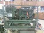
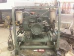
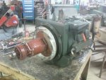
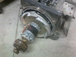
Hey everyone! I got my Mep-016C together last night and am getting no output from it. Anyone know how to test the VR? I have the TMs but got confused on how to test it. :confused:

Engine runs great, just a little smoke at startup/shutdown.
 

Attachments

mikev

Active member
Steel Soldiers Supporter
254
72
28
Location
Culleoka, TN
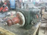
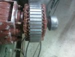
I'm not a genset expert, but that commutator in the third photo looked corroded over. Did you clean it to a shiny finish before reassembling?

Also, search "flashing a generator"...

Our resident gensets experts will probably reply with better info.
 

6x6TRex

Member
261
2
16
Location
Flint, MI
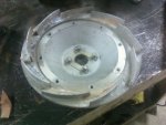
I will try flashing it tomorrow. There is no corrosion on the commutator, just a little on the impeller, but there is a red coating/paint on it.

I just got done running it again, took some videos but they didnt turn out good, will take some more tomorrow.

The hertz gauge currently reads ~56 hertz and no voltage. If I push on the throttle, rev it as high as it will go, and adjust the voltage to max I get ~58 hertz and ~50 volts.
 

Attachments

PeterD

New member
622
6
0
Location
Jaffrey, NH
...There is no corrosion on the commutator, just a little on the impeller, but there is a red coating/paint on it...
Read coating/paint? On the commutator? That thing has to be shiny copper to work, that red stuff will insulate it and you won't get any output! :wink:
 

mikev

Active member
Steel Soldiers Supporter
254
72
28
Location
Culleoka, TN
So instead of looking like the first picture, it should look like the second?
Yep and in that second picture you need more work on shining up that commutator. Read: bright and shiny copper...

EDIT: If that second pic is your MEP...???
 

quickfarms

Well-known member
3,495
25
48
Location
Orange Junction, CA
Could the red paint be a anti corrosion protection for storage?

Is there any way to test the conductivity of the red coating?

There is such a thing as conductive paint, just google it

Does the tm include a test procedure?
 
Last edited:

PeterD

New member
622
6
0
Location
Jaffrey, NH
Could the red paint be a anti corrosion protection for storage?

Is there any way to test the conductivity of the red coating?

There is such a thing as conductive paint, just google it

Does the tm include a test procedure?

Probably not storage paint, the red stuff is an insulating paint put on windings to insulate. But not put on like the pictures show--that was a total fubar. It is a fairly tough paint, you need to clean off the area where the brushes are supposed to contact.
 

6x6TRex

Member
261
2
16
Location
Flint, MI
Did you flash it?
I did using this method, but my batteries were dead. Going to get some new ones and try again tomorrow.
From TM 5-6115-271-14
Flashing the field without a switch
1. open or remove control box cover
2. Connect two 1.5 volt batteries in series and connect a wire to each end.
3. connect the positive wire from the batteries to terminal No. 20 on the voltage regulator.
4. start the generator set
5. momentarily touch the negative wire to terminal No.21 on the voltage regulator to flash the field.
 

Speddmon

Blind squirrel rehabiltator
Super Moderator
Steel Soldiers Supporter
4,640
28
38
Location
Cambridge, Ohio
I don't really know anything about the 016's at all, but I can tell you for a fact that what all of you are referring to as the commutator in those pics is definitely NOT a commutator.

Reasons being...

First and foremost, these generators like it's bigger brothers in the MEP series are "Brushless" generator heads. You HAVE to have brushes in order to have a commutator.

Secondly, commutator segments are made of copper not steel as can be clearly seen in the last picture posted of the shiny clean surface.

What you folks are looking at is more than likely the rotating field winding, and it should indeed have the red paint on it (which is not paint either by the way, it's an insulating varnish).

As to the lack of power output, you can apply 12 volts to the exciter wires of the VR going to the field and see if you get any output. If yes, the VR is the problem, if not the generator head is the problem. Don't ask me which wires you need to use, because I don't have a clue.
 

derf

Member
926
13
18
Location
LA
^ I think he's right. No brushes, no commutator.

That should be the exciter armature. There should be some diodes somewhere around it. In a brushless gen the exciter field energizes the exciter armature which feeds the main field DC which energizes the main armature.

You regulate DC to the exciter field to control output. The exciter armature rotates inside the regulated DC field and makes AC which is rectified by the diodes to feed DC to the main field which rotates inside the main armature AC power is taken from the main armature.

See pic.
 

Attachments

Top