• Steel Soldiers now has a few new forums, read more about it at: New Munitions Forums!

  • Microsoft MSN, Live, Hotmail, Outlook email users may not be receiving emails. We are working to resolve this issue. Please add support@steelsoldiers.com to your trusted contacts.


Scratchbuilt 1/8 scale M915A1

BrassBuilder

Member
30
0
6
Location
Mitchell, SD
Hey all,
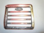
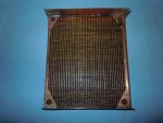
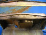
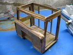
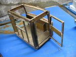
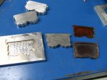
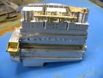
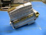
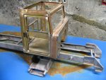
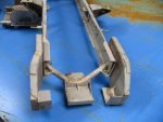
Been a lurker here for awhile. I stop in once every couple of weeks. I'm building a 1/8 scale M915A1 and thought I'd post some pics of what I have done so far. This is just going to be a few random shots without a lot of indepth explaining. I'm also posting more pics on my website at www.firesteelhobbies.com.

I'll see about posting more updates here.

Mike
 

Attachments

BrassBuilder

Member
30
0
6
Location
Mitchell, SD
Thanks.

A little backstory to this. I work for the Guards as a computer tech now. A few years ago, the shop got a contract to rebuild about 40 of these. Tore them right down to the frame. I had hundreds and hundreds of pictures of a tore down M915A1. I say "had" because I somehow deleted them all while I was working on a couple of college degrees and I switched computers about 3 or 4 times. But not to worry! A friend owns 4 of these and he let me take all the pictures I needed. He also had one truck in quite a few pieces which was really nice. All in all, I got over 1000 pics and hundreds of measurements.

I've been working on this since 2008, but I took a break in there to get a Bachelor and Master degrees and I also spent a considerable amount of time CNCing my 12x lathe. But the degrees are done and the lathe is CNCd, so now I have fun time available.

Mike
 

doghead

4 Star General /Moderator
Staff member
Super Moderator
Steel Soldiers Supporter
26,247
1,166
113
Location
NY
Awesome!

I can't wait to see more!
 

BrassBuilder

Member
30
0
6
Location
Mitchell, SD
I should be back on this build in a week or so. I had a bunch of military training to go to and then I had two roofs to build. I got most of the projects done and looking forward to getting back to this.

Thanks for all the great words!

Mike
 

Kaiserjeeps

Member
459
7
18
Location
North Idaho in the woods
Just found this thread. Very nice! Have you seen the method of photo etching brass to make parts? Or are you already doing that?
Some of the scale ship forums have great info on photo etching brass. I want to learn that. I have found working rockwells in miniature if you are going to RC the rig. Might be the wrong scale though.

I am working on a 5 foot UK tug boat.
Looking forward to seeing the progress. Great work!
 

BrassBuilder

Member
30
0
6
Location
Mitchell, SD
It's going to be a static display model. I am striving to put as many of the details in this as I can. I'm working off of around 1400 pictures of every imaginable angle on this truck. I probably have around 300 or 400 measurements, but I plan on getting more measurements before I deploy to Afghanistan in July. I am hoping to have some time to work with my CAD programs and get some of the machining drawings made and the g-code generated while I am there.

I am working on some photoetched parts right now. It's taken me a while to figure out a system that worked for me. I am using an actual photo etch paper to make the masks and it seems to work much much better than the Press n Peel Blue or trying to use laser photo paper and the ink transfer method. And actually....the PnP Blue works good....it just depends on what you are making. However, the photo etching takes more equipment and chemicals than the PnP or laser photo paper. There are pros and cons with both.

I'm in the process of rebuilding the radiator that I posted earlier. I think I can do better than what I got.

Here are a few pics of the individual radiator fins that I am making:

artwork2.jpgThis is the mask printed on transparency. This gets taped together so that the brass or aluminum can slip in between the two sheets. I have found I get much better results by etching from both sides....hence the mask that needs to be on both sides.

artwork4.jpgThis has the transparency taped so that both sides line up EXACTLY and then the .002" brass shim stock is inserted in between.

DSCN1027.jpgHere it is after the resist is applied and set under the exposure lamp for 3 minutes.

DSCN0976.jpgAnd here it is after running through the etchant. I get four fins per run (I need around 200). I still need to cut these apart.

This was a very simple and condensed version of what actually takes place. If anyone wants detailed instructions on what I am doing, let me know and I'll post a link to another forum where I explain all of this in-depth. I am also going to get something on my website about photoetching.

Mike
 

trukhead

New member
725
5
0
Location
dane/wi
AAamazing! If one where to convince one of those micro model engine builders to make a working scale 250 and get a set of those working model rockwells and make up a tiny transmission and transfer case and tiny steering box..........
My brain is starting to spin like Linda Blair in the Exorcist ........
Fantastic Model!
It's fun to read this thread!:popcorn: :grd:

Do you use a soldering iron or resistance soldering setup?
 
Last edited:

BrassBuilder

Member
30
0
6
Location
Mitchell, SD
AAamazing! If one where to convince one of those micro model engine builders to make a working scale 250 and get a set of those working model rockwells and make up a tiny transmission and transfer case and tiny steering box..........
My brain is starting to spin like Linda Blair in the Exorcist ........
Fantastic Model!
It's fun to read this thread!:popcorn: :grd:

Do you use a soldering iron or resistance soldering setup?
LOL...I would LOVE to make the engine, transmission, and transfer case actually work, but my limited machining knowledge would never get that done....or it would take me 100 years to figure it out.

I have both a soldering iron and a resistance soldering setup plus a number of small butane torches. I'm experimenting with using the soldering iron to get all the individual fins soldered to the strips representing the tubes. I super glued the first radiator together which didn't turn out bad, but just not as good as I think I can do. As there will only be around .025" between each fin, I need to figure out a technique to use solder sparingly so as not to glob. I have not had much luck with the resistance soldering unit that I have...but that is most likely due to operator error.

And that, my friends, is my big issue right now. It is harder to do than it appears since I have parts so close together. Compound that with the fact there are 42 "tubes" and around 100 fins (or so), I am looking at approximately 4200 individual solder joints.

Mike
 
Top
AdBlock Detected

We get it, advertisements are annoying!

Sure, ad-blocking software does a great job at blocking ads, but it also blocks useful features of our website like our supporting vendors. Their ads help keep Steel Soldiers going. Please consider disabling your ad blockers for the site. Thanks!

I've Disabled AdBlock
No Thanks