View attachment 530988View attachment 530991View attachment 530992View attachment 530993View attachment 530994
Jason, it is evident you are not familiar with older engine design. They did NOT have complete oil filtration until the mid to late 1950's . My 1954 Chevy Truck is a prime example. Look it up before making such broad statements. I'm posting pictures of what the oil pressure is AT the filter housing. The filters are NOT getting the full 100 PSI. I have studied the valving in the regulator diagrams and I have made actual tests. If the filters where designed for full filtration then the oil bypass pressure would NOT be 15 PSI but something in the order of 40 PSI to 50 PSI like a modern engine. Again look it up. The purpose of a bypass is to prevent over pressure of the filters when they become clogged. NO modern engine has there bypass pressure set at 15 PSI. If it was true that the main pressure was to keep the filters from blowing up, then how do you explain the 100 PSI at the filter housing ? According to you it would be 40 PSI. Before you start to "lambast me" again, please provide proof like I am right now.
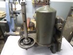
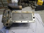
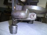
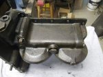
The first picture shows the pressure before engine start-up.
The second picture shows engine pressure at idle (750 RPM's) .
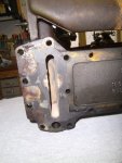
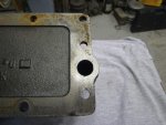
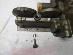
The third picture shows where the test port is with my mechanical gauge installed.
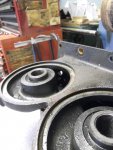
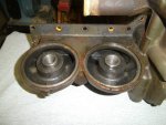
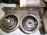
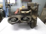
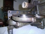
The fourth picture shows the location of the oil filter bypass.
The fifth picture shows the location of the oil cooler bypass.
You wrote: "Jason, it is evident you are not familiar with older engine design."
I have owned about a half dozen 270 & 302 gmcs and am well familiar with the block and oil galley modifications necessary to convert them to full flow oil filtration. I have converted two Reo OA331 from bypass to full flow filtration.
You wrote: "They did NOT have complete oil filtration until the mid to late 1950's."
Winslow developed them in the 1930s and installed them in Hall Scott engines. Waukesha and other industrial engines used them later on. Chrysler had them in 1946 (look this up in the GMC Speed Manual published by Bill Fisher in 1955).
You wrote: "If the filters where designed for full filtration then the oil bypass pressure would NOT be 15 PSI but something in the order of 40 PSI to 50 PSI like a modern engine."
Not sure if you are trying to state the multi doesn't have full flow filtration but if so you are completely wrong. If not, my apologizes for the misinterpretation. However, TM 9-2815-204-35 states "Pressurized oil is forced through the filters BEFORE entering the oil cooler and engine lubricating system.... ...The bypass valve opens at a differential pressjure of 15psi." This is the definition of full flow oil filtration.
Look at the oiling diagram for the multi and compare it to a modern cummins engine.
http://www.beamalarm.com/Documents/cummins_system_diagrams.html With the exception that the cooler and filter are switched around, they are they are virtually identical. The multi has a modern full flow oiling system!
You wrote: "NO modern engine has there bypass pressure set at 15 PSI. ...the oil bypass pressure would NOT be 15 PSI but something in the order of 40 PSI to 50 PSI like a modern engine. Again look it up."
You can find this statement in the 2004 NAPA/ Wix catalog: "Typically, engine manufacturers design bypass valves to open at a pressure differential of approximately 10 to 30 psid" This is the valve which keeps the center tube from collapsing due to excessive differential pressure. Look up a typical Ford or Chrysler engine oil filter which will be on the lower range of this. It is the oil galley relief valve that is set to the higher pressure. This is the valve which keeps the filter cans from ballooning. This is also stated in the Wix catalog.
You wrote: "then how do you explain the 100 PSI at the filter housing"
Cold oil. This is not a differential pressure measurement. It is a measurement of the oil galley pressure ("common mode" in electrical terms). If you want to measure the differential pressure, you either need a differential gauge or two gauges and then manually calculate the difference.
I am not trying to lambast you.