• Steel Soldiers now has a few new forums, read more about it at: New Munitions Forums!

  • Microsoft MSN, Live, Hotmail, Outlook email users may not be receiving emails. We are working to resolve this issue. Please add support@steelsoldiers.com to your trusted contacts.

MEP-003A Exhaust Idea

1oldiron

New member
4
0
0
Location
Redmond, Washington
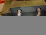
Having purchased and installed two MEP-003A gensets, the issue of routing exhaust gases from two outlets raised some questions. Adding too much cantilevered weight of iron pipe off the muffler outlets looked to potentially create vibration and fatigue problems. Buying two long lengths of flex pipe did not seem the best idea either. Just in case anyone with a similar question might appreciate a novel approach, a photo is below along with a short description and the source of the one key part:
Manifold with Union.jpg

Sorry about the tiny photo. I will be glad to email a full size version if requested


Since only one 45* street elbow is required, the other had to be removed. The other issue was that the ID of the 1 3/4" flex pipe does not mate up with the OD of the 1 1/4" iron pipe. The choice was to either turn the OD of the iron pipe down to 1.380" - way too thin - and use 1 1/2" flex pipe, or build it up to fit the ID of the 1 3/4" flex pipe. Therefore the three nipples that attach to the sections of flex pipe were turned down slightly, a short piece of 1 3/4 OD exhaust tubing slipped over and brazed into place.
The key part is the 45* 1 1/4" Anvil Y. It is available from Grainger as part # 4WHU6. The rest of the stuff is off the shelf 1 1/4" elbows, nipples, and a union. If you do not have a couple huge wrenches to tighten the union, two 1 1/4 floor flanges with a chunk of Mr. Gasket header gasket material between works fine. I rigged the second unit that way since there is not a huge tool selection at the place it is installed.
You will notice the short section of flex pipe between the outlets. That is because there is no way to assemble this setup without a gap between the threaded outlets. It also compensates for the fact that a perfect alignment is basically impossible, and serves as a vibration and expansion isolator between the mufflers.
The method is to assemble the elbows and Y first and then slip the two built up nipples into the flex pipe. Then start both nipples into their respective female threads with the flex pipe in place. Once both nipples are tight, install the pipe clamps over the flex pipe.

I hope this helps a few who may still be trying to decide on the exhaust solution.
Jeff Howard
Redmond, Washington
 

Attachments

Last edited by a moderator:

cuad4u

Active member
268
88
28
Location
St Matthews, SC
Interesting concept and I hope it works well. In order for any engine to perform properly it must be able to breathe. That means the engine must be able to freely "inhale" and freely "exhale". The exhale part is the exhaust. If the intake air, fuel or exhaust is restricted the engine cannot perform well. I would be careful about combining the two exhaust outlets into one exhaust pipe of the same or a smaller diameter. I really cannot tell from the picture. Restricting the exhaust can choke the engine power just as much as restricting the incoming air or fuel. On the other hand these 003A diesels are just loafing at 10KW so combining the exhaust gasses of all 4 cylinders into one exhaust pipe probably will not restrict the exhaust (exhaling) of the engine noticeably.
 

rustystud

Well-known member
9,178
2,742
113
Location
Woodinville, Washington
I agree with "cuad4u" about the size of your exhaust pipe. You probably should up-grade to a 1" larger pipe (at least) for your final size. Especially if your moving the exhaust more then 4 feet.
Looks good otherwise !
 

1oldiron

New member
4
0
0
Location
Redmond, Washington
Thank you for the input. I checked a few exhaust pipe size calculators and it appears that a pipe will efficiently flow 115 cu/ft per minute per 1 sq/in of area. A 1 1/2" pipe, .065" wall, has 1.48 sq/in of area. It should therefore pass up to 171 CFM. The 120 cu/in Onan displaces only 62.5 CFM at 1,800 RPM. Even adding an allowance for heat expansion due to combustion, it would get nowhere near the capacity of the piping system. Another quick and dirty calculator uses maximum horsepower to calculate minimum pipe sizes. It reads that a 1 1/2" pipe is capable of passing exhaust for 92 HP. That is also based on a gasoline engine that has higher exhaust temperatures than a diesel. The Onan engine makes all of 17.8 HP at 1,800.

I have run both machines up to and holding nearly 12KW simultaneously running a phase converter, a 7 1/2 HP air compressor, and 7 1/2 HP lathe along with lights and a few welding passes. They both seem very happy in their work.

All the Best.
 

rustystud

Well-known member
9,178
2,742
113
Location
Woodinville, Washington
Thank you for the input. I checked a few exhaust pipe size calculators and it appears that a pipe will efficiently flow 115 cu/ft per minute per 1 sq/in of area. A 1 1/2" pipe, .065" wall, has 1.48 sq/in of area. It should therefore pass up to 171 CFM. The 120 cu/in Onan displaces only 62.5 CFM at 1,800 RPM. Even adding an allowance for heat expansion due to combustion, it would get nowhere near the capacity of the piping system. Another quick and dirty calculator uses maximum horsepower to calculate minimum pipe sizes. It reads that a 1 1/2" pipe is capable of passing exhaust for 92 HP. That is also based on a gasoline engine that has higher exhaust temperatures than a diesel. The Onan engine makes all of 17.8 HP at 1,800.

I have run both machines up to and holding nearly 12KW simultaneously running a phase converter, a 7 1/2 HP air compressor, and 7 1/2 HP lathe along with lights and a few welding passes. They both seem very happy in their work.

All the Best.
Now see that's engineer talk. As a mechanic I see things from a practical point of view. When a manufacture says his exhaust system is perfectly capable of working with a 1.5" line I say great. Then change it out to a 2.5" pipe and gain 50HP. One thing I have found out in all my years wrenching is there is the theoretical and there is the practical. The engineers come up with the theory's and mechanics must put them into practice.
 

SCSG-G4

PSVB 3003
Steel Soldiers Supporter
5,331
3,272
113
Location
Lexington, South Carolina
I agree with Rusty on this. Theory is a good place to start, but bigger pipes have less turbulence and less internal pressure so the engine does not have as much work to do pushing the exhaust air out. Less effort expended on the exhaust, more effort that can be applied to other things. What theory fails to recognize is that there is 'friction' or 'resistance' to the airflow close to the walls of the pipe. The larger the pipe, the larger the free flowing diameter (IE, a 1/2 in diameter pipe only has a 1/4 diameter free flow cross sectional area, a 1 inch pipe about 3/4 inch, a 3 inch pipe has about 2.5 inches of free flow area). The longer the pipe and the more turns, the more turbulence there is, and therefore more back pressure. YMMV.
 

cuad4u

Active member
268
88
28
Location
St Matthews, SC
While in theory a small exhaust pipe may be adequate especially in this situation, in the real world a larger exhaust pipe (up to a point and with diminishing returns) will offer less restriction to the hot gasses exiting the engine. A larger exhaust pipe (up to a point) will result in better "breathing" (what goes in must come out) and better engine performance, possible better engine efficiency, and possible cooler engine operation - especially in an air cooled engine.

For example I have a Ford F-250 with the V8 diesel engine. The factory installed exhaust system was a 3 inch pipe coming from each exhaust manifold which connect together just behind the engine at a Y with a single 3 inch exhaust pipe to the rear of the truck. At age 66 I was not interested in "hot rodding" the truck but in order to hopefully improve engine performance, I replaced the very small (much too small IMO) stock air filter with a much larger free flowing after market air filter assembly. At the same time I installed dual 3 inch exhaust pipes from each exhaust manifold and ran dual 3 inch exhaust pipes to the rear of the truck. I do not have access to a dynamometer but just from seat-of-the-pants feeling, the increase in engine performance is quite noticeable. Mileage increased by at least 1-2 MPG.

Just my $0.02

Dick - PE Electrical Engineering and a half-ass mechanic
 

DieselAddict

Well-known member
Steel Soldiers Supporter
2,489
1,902
113
Location
Efland, NC
One of the things to consider with exhaust flow is how it happens. The flow from the engine isn't smooth and constant. When you put your hand in front of the port you feel the puffs. This means the dynamic conditions of the exhaust are very different from doing basic calculations which assume average flow. When the exhaust valve opens air rushes out at reasonably high velocity that creates a pressure gradient in the exhaust tube. As the gas moves down the tube the gradient will spread out. That means the leading edge will be moving faster and the trailing edge will be moving slower. The leading edge will see more resistance but the trailing edge will see less. Since this isn't constant flow the calculations get a lot more complex.

With a 1.5" tube I'm not worried about gas flows and pressure gradients being so high to seriously affect performance. What I would be more concerned about looking at this arrangement is how things are brought together at the (Y) and how engine timing (exhaust pulse timing) can affect performance. Specifically if a high pressure zone is moving past the "Y" fitting when an exhaust valve for #1 or #2 cylinders opens the exhaust from those cylinders will bump into that slug of hot compressed gas from cylinders 3+4. In my opinion this has a higher potential affect on engine performance than the resistance of the tubing. Even so I would expect the performance hit worse case to be in the 5% range.

One of the best ways to look at exhaust performance is with temperature. Anywhere you have gasses stacking up you will see a hot spot in the exhaust. This is the basis of looking at the "bluing" on headers in the olden days to see how they were flowing.

Anyway, before I go off in the weeds I'll stop and say that the arrangement above isn't great since you could easily have much higher than normal pressure at the "Y" because of the length of the tube between the two exhaust ports. However, in this application it shouldn't be a serious issue with performance. The looses from it being suboptimal are modest. I would take some EGT readings to make sure you aren't causing any hot spots near the head that could translate into increased exhaust valve wear over time. This is an air cooled engine and head temp is one of the important things to monitor. I've considered adding some thermocouples to keep track of the head temp on my 003.
 

wb1895

Member
876
16
18
Location
Lexington NC
I would also be concerned with carbon build-up inside that small of a pipe. It seems to me that just a small amount of carbon will drastically reduce the amount of flow, thus causing the engine to work harder, less efficiently, and causing carbon to build up that much faster. Just my .02 cents
 

Triple Jim

Well-known member
1,373
277
83
Location
North Carolina
1oldiron already load tested the generator to 12 kW without incident. Now if he runs it for a few tens of hours he can find out if there are any problems with the system like carbon buildup, etc.. Let's take this as an opportunity to learn some things about 003A exhaust systems. :beer:
 

rustystud

Well-known member
9,178
2,742
113
Location
Woodinville, Washington
Actually "DieselAddict" hit in on the head pretty good with his post. I ran my house with generators for 10 years. In that time I learned quite a bit about exhaust systems and air cooled engines. As a mechanic I know all about the sizing of the manifolds to get proper scavenging effects and the effects of friction (lets polish some ports ! ) but what I didn't know at the time was the effect of back pressure on the heads of air-cooled engines. Since I didn't want the exhaust staying in the building I built a great ( I thought ) stainless steel pipe exhaust system with heat wrap. The problem was I didn't allow enough size in the pipe. According to the books the size was perfect. What ended up happening was the exhaust valves got so hot they melted down into the engine block . This happened to 3 engines ! You would think I would have learned from the first engine. :doh: After the third engine I sat down and tried to figure out what was happening. I own several "Manometers" and temperature gauges, so I installed some. What I found was too much "back pressure" . The engine was having to "push" this HOT gas down a pipe over 10ft long and the heat never got a chance to leave the head area due to pressure from the long pipe. According to all the engineers data the pipe size was fine as was the amount of back pressure. But in the real world I needed to go to a 1 inch larger size pipe due to the length I was pushing. When I increased the pipe size I was able to lower the pressure at the exhaust valves which in turn lowered the temperature since the gas was able to flow more freely. In automotive engines you need a certain amount of back pressure to actually make the engines run more efficiently, but in a air cooled single RPM engine this is a bad thing. Actually in our air cooled engines if you just dumped the exhaust into a 6" or larger pipe it would be just fine. If you think about it the pipes as they stand now are the ends of the exhaust system. We are adding an extra burden to them when we extend them to run outside our buildings. These engines where never designed to have long exhaust pipes. They go to the muffler then out. Sure the engine tested fine at 12KW but for how long ? What did it test out to before the extra length of exhaust pipe ? On all my generators, if I need to lengthen the exhaust system I go with a LARGE pipe. No more melted exhaust valves for me.
 

cuad4u

Active member
268
88
28
Location
St Matthews, SC
I hope the original poster was not offended by those of us (including myself) who expressed possible concern over the 003A exhaust system he showed. If so that was not my intent.

As explained in my post and by others, getting rid of HOT exhaust gasses can be a bit more complicated than just running a pipe from the engine to "where ever".

IMO there are two major items to be considered here. The first concern is how the HOT exhaust gasses are removed from the engine and the second concern is this is an air cooled engine. Heat generated in and removal from air cooled engines VS water cooled engines is an entire separate subject that is beyond the scope of this discussion.

As anyone who works with engines knows, depending on how they are routed, exhaust gas pulses can HELP or HINDER scavenging the hot exhaust gasses and heat from the engine. That is why high performance exhaust headers have what looks like a convoluted tangle of pipes running "every which a way". The configuration of the header pipes uses exhaust gas pulses to create a vacuum which helps evacuate hot exhaust gas from the cylinders, increases engine efficiency and power, and which also aids in the removal of heat of combustion. IMO removing heat from the cylinder is more important in an air cooled engine VS a water cooled engine. See rustystud's comments about melted exhaust valves.

On the other hand, if exhaust gas pulses are restricted, this may result in back pressure which inhibits the removal of spent hot exhaust gases and heat from the cylinders. Actually back pressure tends to keep hot exhaust gases and heat in the cylinder instead of removing it.

I think that is why it was recommended to use an infra-red heat sensor to see if any hot spots show up in the recommended configuration.

Finally I do not think anyone was "throwing rocks" at the original suggestion. At least that was not my intent. Apologies if anyone was offended.
 
Last edited:
Top
AdBlock Detected

We get it, advertisements are annoying!

Sure, ad-blocking software does a great job at blocking ads, but it also blocks useful features of our website like our supporting vendors. Their ads help keep Steel Soldiers going. Please consider disabling your ad blockers for the site. Thanks!

I've Disabled AdBlock
No Thanks