• Steel Soldiers now has a few new forums, read more about it at: New Munitions Forums!

  • Microsoft MSN, Live, Hotmail, Outlook email users may not be receiving emails. We are working to resolve this issue. Please add support@steelsoldiers.com to your trusted contacts.

MEP-004A, No output

peapvp

Well-known member
Steel Soldiers Supporter
1,118
1,244
113
Location
Basehor, KS
Repair and Test of an A11 Static Exciter Unit for MEP004A/005A

As Kris pointed out, I will be detailing here the tests and results of testing Kris's A11 unit which had a visibly burnt out T2 Transformer during the repair.

There are a total of 5 tests which were performed according to the Manual TM 9-6115-464-34 Pages 3-276 and 3-277

I will post each test with pictures and a more in depth explanation here over the next 2 or 3 days.

I have attached 48 extracted pages of TM 9-6115-464-34 which cover the entire static exciter section for reference and ease of use for the interested reader in pdf format.

The very last post will be in reference to the replacement transformer T2 which we had chosen to start the repair.

So far upfront on T2 - the replacement Transformers Primary Winding's have to be reduced in order to obtain the original Transfers Ratio.

The original Transformer had the fairly bizarre Transfer Ratio of

208VAC to 128VAC = 1.675:1

All most all Center Taped off the shelf transformers today have a Transfer Ratio of

240VAC to 120VAC = 2:1

so, both primary winding's of the replacement transformer will have to be reduced by a total of 0.325 of the total winding count, that is by 0.1625 of each primary winding count since they are connected in series ( 2x 120VAC Center Tapped)

This may sound complicated but it isn't [contact me if you want to buy a already modified T2 Transformer based on a new COTS TR]

It will be next to impossible to find a Transformer today with a 1.675:1 turn Ratio with a VA Rating between 100VA to 300VA


I will also bury a myth which has floated around here on SS for quite a while now connecting a failed T2 Transformer with Sewerzuk's output reconnection board modification to convert the 3 Phase system to a single Phase 208/120VAC system.

Sofar upfront: THE MOD, whether done exactly like in Sewerzuk's Video on Youtube or by forgetting to move the control wires beneath the Output Reconnection Board WILL NOT OVERLOAD / BURN UP T2 Transformer

This conclusion is simply wrong.

I WILL NOT GET INVOLVED IN THE DISCUSSION IF THIS MOD IS GOOD OR BAD TO BEGIN WITH

I CAN TELL YOU ONLY ONE THING: I AM A FIRM BELIEVER IN USING A DELTA / WYE TRANSFORMER TO LET THE IRON DO THE CONVERSION AND BECAUSE I WANT ALL OF THE AVAILABLE POWER TO BE AVAILABLE IN CONVERSION.

Enough said.


The Actual and only cause of T2 burning out is simply the lack of a simple 3 Amp Fuse on the Primary H1 Line.

The directly connected C2 SCR Capacitor fails with age and causes a increasing current draw which is just short of being a short on the secondary side between X1 and X3 which causes T2, because of lack of proper fusing, to burn out over a period of time

This is not an instant failure but one which occurs over a period of time. I would say it could take 15 minutes to 60 minutes once this increased current draw starts to burn out T2


View attachment TM-9-6115-464-34 Static Exciter Section Only.pdf
 
Last edited:

peapvp

Well-known member
Steel Soldiers Supporter
1,118
1,244
113
Location
Basehor, KS
Test 1 - Repair and Test of an A11 Static Exciter Unit for MEP004A/005A

First test as per Manual TM 9-6115-464-34 Pages 3-276 and 3-277

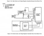
This test verifies the correct operation of the Voltage Regulator Board

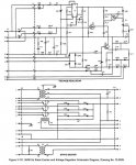
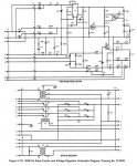
004A VR.jpg

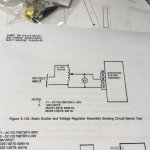
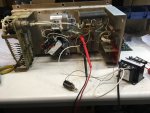
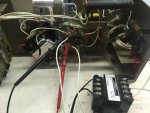
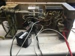
The test setup is as follows:

69879143_390929688291112_1481531020086870016_n.jpg

I use a isolation transformer for anything which requires a Voltage higher then 48 V AC/DC

70187226_364604851129138_7012967989846736896_n.jpg

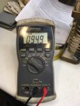
I am also using a 1KOhm 10 Turn 10W Potentiometer to adjust the input Voltage to 95 VAC on the input. I am connecting directly to T3 H1 and H2 but have tested the J9 A and B pins for continuity, I also checked R2 for correct connection and resistance before applying power

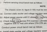
Manual calls for:
69851708_2390397721176733_4875557564869246976_n.jpg


And we have applied 94.9 VAC
69405394_471612300059431_7155956307353141248_n.jpg


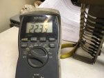
And the result across R15:

69905003_669192333585301_5099363251192332288_n.jpg


Test 1 passed

This is the first test to check the VR Board
 

peapvp

Well-known member
Steel Soldiers Supporter
1,118
1,244
113
Location
Basehor, KS
General Information on Test Equipment and validating Test Results

You may have noticed that the TM's generally ask you to check for a particular Voltage, Current, Resistance etc.

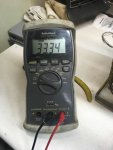
You also may have noticed that I am using a Radio Shack DMM for testing.

This has two primary reasons:

I have owned three off these since they were introduced by Radio Shack in the late 90's as they have a RS-232 Output and a capturing software which I am still using on my Lab PC

I calibrate my Test Equipment to NIST Calibration Standards - I own several HP Ultra High End Signal Generators with DMM, Oscilloscopes and Spectrum Analyzers which are all NIST calibrated - I could have bought a House for the money spent o this equipment over the years.

So, I can check the accuracy of any test equipment to reference Voltage / Currents and verify correct operations.


Interestingly enough, this particular Radio Shack DMM had the highest accuracy over the entire measurement range of less then 0.01% when compared to other High End DMM's with a significant higher price tag.

After I had bought my first Radio Shack DMM and checked for accuracy, I sold all my high end DMM's on eBay decades ago........

The results here presented to you are accurate to 0,01%

Now, like in our first test the Manual asked us to test on R15 for 22VDC with an input of 95VAC (We had 94.9V)

The result was 22.35 VDC -

The question now is, is still good or already bad?

Now remember, the Radio Radio Shack DMM's tolerance are 0.01%

The passive parts (resistors, capacitors etc) on the VR Board have tolerances of 1%, 5%, 10% and 20%

to evaluate a Potential or Current we have to locate the resistor/diode with the lowest tolerance on the to be tested circuit.


A chain is only as strong as it's weakest link.


Here on the VR Board its the resistors and the Diodes used with 10% tolerance

This gives us the tolerance which the Manual does not provide for a test to pass or fail

In our case its 22V +/- 10% that would be 19.8VDC to 24.2VDC

Your VR Board passes the first test if your test result is between 19.8VDC to 24.2VDC

But, of course as closer to 22VDC you are, the better

In our case we are +1.5% higher, and that is excellent - because the Radio Shack DMM's accuracy is 0.01% and that means that is has no impact at all.

And one last thing:

We usually do not repair any equipment at INOVA HIGHTECH since we are primarily a R&D Facility and manufacture Military and Industrial OEM equipment during our normal course of business.
 
Last edited:

peapvp

Well-known member
Steel Soldiers Supporter
1,118
1,244
113
Location
Basehor, KS
Test 2 - Repair and Test of an A11 Static Exciter Unit for MEP004A/005A

This post will describe Test 2, Power Test of the A11 Unit as per Manual TM 9-6115-464-34 Pages 3-276 and 3-277

We have replaced T2 with a COTS 2:1 100VA Power transformer with a Center-tapped primary and secondary winding system and we have replaced C2 with the lower cost SCR/Motor Run Capacitor as previously shown in the older posts under this thread.

Kris and I agreed to go this lower cost route (about $ 50.00 for both parts) to demonstrate to the interested reader that a repair can be successfully accomplished by using regular parts.

Remember, Mouser etc. still sell the original C2 but the correct part number unit is a 100pcs minimum buy with a cost of $ 75.00/ea - so if you want to replace C2 with the exact original one you would have to order 100pcs which equates to $ 7,500.00
as the Manufacturer of C2 has to make a special production run for you.....

This test basically verifies two parts in the A11 Unit:

1.) It verifies that the two Silicone Rectifiers G1, G2 and the Diodes CR7, CR8, CR16, CR17 and the Zener Diode VR1 and the Integrated Circuit U1 are working correctly

2.) It verifies that T2 and C2 are working correctly


Power test setup.jpg
70556198_526855201416868_7650510646047408128_n.jpg004A VR.jpg

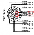
The power as required is applied here directly to H1 and H2 (new TR H4) for simplicity reasons instead of working through a multi pin connector - Connections to/from J13 L and M Pin were verified by the means of a continuity test.

The test asked us to apply 208VAC to L/M J13 Pins. But I used a slightly lower Voltage to verify two issues:

1.) To see on how the Transfer Ratio of the new replacement Transformer T2 which is 2:1 is going to affect this circuit

2.) To verify that a lower Input Voltage on T2 does not increase the current through the Static Exciter Coil F1/F2 which was suspected in connection with Sewerzuk's Voltage Reconnection Board modification in other posts as a cause of T2 burning out

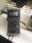
So, I applied 200VAC through my 50VA isolation transformer which resulted, due to the load of A11, to 185.8VAC on T2 H1, H2


69561032_2502411203115295_4392965238375317504_n.jpg


I did this on purpose. The Voltage drop of 14.2VAC told me two things:

1.) The entire Power Test is good - A11 and VR Board work as intended and this circuit uses more then 50VA even without the Static Exciter Coil F1/F2 connected

2.) The load (Coil) is not a current load, meaning it will not get more then the 1 Amp currently drawn by this cirucit


Next thing was to check the Output DC Voltage across Pins R and S on J13 which connect from J13 directly to F1/F2 via Terminal Board TB1

I connected the DMM to the Heatsinks of CR1-3 (Plus) and the Center Tap X2 of T2 (Minus) after verifying that R and S have continuity to those points (Follow Schematic above X2, J13 R and J9 D for Minus and J13 S, J9 C and CR1-3 for Plus)

70338547_2396559350420339_7980728270297497600_n.jpgJ13.png


We are supposed to measure 48VDC but we got (see explanation why in first pic here):


Power Test.jpg69689930_463196037861203_1877818474143678464_n.jpg

Conclusion:

The new replacement Transformer T2's primary winding count has to be reduced from the present transfer ratio from 2:1 to 1.625:1 by physically removing the terminal board on the top of the primary side (desoldering the leads) and then carefully removing the plastic covers to expose the coils. The primary winding's on those type of transformers are the outer coil systems, the secondary winding's are on the inside, hence not accessible unless the primary winding's are removed first.

And

because this design is a constant load on T2, regulating the current through U1 and the two SCR's G1 and G2 whether or not a load is attached to R/S J13 and has no impact on overheating T2, regardless of the AC Voltage applied on H1 / H2
and therefor IT CAN BE RULED OUT as CAUSE OF OVERHEATING OF T2 AS A RESULT OF A INCOMPLETE / FAULTY EXECUTION OF ZEWERSUK's VOLTAGE RECONNECTION BOARD MODIFICATION TO CONVERT FROM A 3 PHASE TO A SINGLE PHASE SYSTEM.

This concludes Test 2, but we will conduct Test 2 again after T2 has been modified
 
Last edited:

KLChurch

New member
475
2
0
Location
Montgomery/TX
They were only 27 dollars verses 1800 dollars and I thought I might need a spare since I did not know what caused the original to be toast.
Kris
 

peapvp

Well-known member
Steel Soldiers Supporter
1,118
1,244
113
Location
Basehor, KS
I hope this works better then the Klein small Side Cutter I got to cut pins of components after soldering (for those parts which are hand soldered).
Those cutters brake every 8 month or so and I am now on the fourth replacement under their lifetime warranty....


View attachment 775642

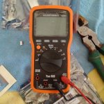
This is the DMM I have been using. Also I have an analogue.
Kris
 

peapvp

Well-known member
Steel Soldiers Supporter
1,118
1,244
113
Location
Basehor, KS
Datasheet U1 UA723HM

Ok, I am adding the Datasheet for U1 here which is a Precision Voltage Regulator UA723HM which is the Metal Can, extended temperature version and they are still available
This Precision Voltage Regulator limits the current through the static exciter coil and is also used to regulating the overall voltage with the front panel Rheostat / Potentiometer for Voltage adjustment.
I still have to double check on how this potentiometer wires into A11, but I believe it is through R35 in the Special Relay Box connecting through P/J 9 C and D on A11
Hopefully I will be finishing Kris's A11 by Wednesday / Thursday as we had a couple of other things here in the pipeline which also needed to get done.


View attachment FAIRS28167-1.pdf
 

peapvp

Well-known member
Steel Soldiers Supporter
1,118
1,244
113
Location
Basehor, KS
Actually, a DMM to test the final resistance would be enough to modify the Transformer.

As of right now I need to check the wire gauge used to wind the primaries, then I can calculate the actual amount of winding's or turn's the transformer has. This is based on transfer ratio, Voltages, Currents, VA rating and DC resistance.

Once I know on how many turns we got, then I can calculate of how many turns we have to unwind. Its probably anywhere from 10 to 50

All you need to do then is to find the beginning of the coil and start unwinding it by the required turns. Then you cut the excess wire and solder the wire end back onto the Terminal Board. We will do this for each of the two primary coils. The measured DC Resistance on each coil should then be equally within a couple of Ohms or so.

and Kris, I have gotten tired over the years on spending money on name brand tools who then fail shortly after they run out of warranty - best example are the Weller Solder station's. They used to be nearly indestructible, but not anymore.
Every 9 month or so, the Weller WEP70 WEP Soldering Iron, 23V, 70W which plugs into the base unit goes bad - the plastic becomes brittle from the heat and the entire solder tip with heat element falls out of the handle part - cost every time $ 45 to $ 58 plus shipping and on top of this, Weller discontinued the WEP 70, now I gotta buy it as NOS as this renders the base station useless. Weller has not provided a substitute part number and the base station is only 18 month old, same problem with the other ones too....

It's a race to the bottom.


Can you modify the transformer with only a 24 volt power supply to test with?
Kris
 
Top
AdBlock Detected

We get it, advertisements are annoying!

Sure, ad-blocking software does a great job at blocking ads, but it also blocks useful features of our website like our supporting vendors. Their ads help keep Steel Soldiers going. Please consider disabling your ad blockers for the site. Thanks!

I've Disabled AdBlock
No Thanks