• Steel Soldiers now has a few new forums, read more about it at: New Munitions Forums!

  • Microsoft MSN, Live, Hotmail, Outlook email users may not be receiving emails. We are working to resolve this issue. Please add support@steelsoldiers.com to your trusted contacts.

MEP-004A, No output

peapvp

Well-known member
Steel Soldiers Supporter
1,115
1,229
113
Location
Basehor, KS
Correct T2 replacement Transformer

Thanks Brian,

that's pretty much what I got on Kris's unit. I will publish the details later. Kris's A11 is basically ready to go.

However the original Transformer we had sourced doesn't live up to its reputation - the real VA rating is more like 75VA instead of 100VA.....
The load is app 100VA to 120VA and a correct 100VA can handle that. A 1 Amp Fuse should be enough. The wires on the secondary system in A11 are only 18ga!!
So I sourced this one here which has 250VA and doesn't need to be modified, I doubled the VA of what we actually need because the VA ratings today are not as accurate as they once were!
Hammond PH250MGJ Transformer, 250 VA, 50/60Hz

https://www.alliedelec.com/product/hammond-power-solutions/ph250mgj/70191777/
s-l1600.jpg

When we apply 208VAC on this Transformer on the H1 and H3 Input (380VAC/387VAC Input) we will get 129VAC to 131VAC on the secondary between X1 and X4 with X2 and X3 jumpered and being used as X2

View attachment ph250mgj_wd.pdf

This is the closest of the shelf solution

Peter,

Here are the measurements you requested:

H1 / H2 1.8 ohm
X1 / X3 .7 ohm
X1 / X2 .4 ohm
X2 / X3 .4 ohm

I measured 588 mA at H1 (never fluctuated)

Let me know if you need anything else.

Brian
 
Last edited:

peapvp

Well-known member
Steel Soldiers Supporter
1,115
1,229
113
Location
Basehor, KS
Kris,

there is a bottom bar on each post where you can click thank you on someone else's post.

On the posts you posted there is a clickable link to the right:

kris.jpg


I don't know how to edit or add to a previous post.
Does anyone know how?
 

peapvp

Well-known member
Steel Soldiers Supporter
1,115
1,229
113
Location
Basehor, KS
Replacement Transformer Issues

So, to cut through the chase - the first replacement Transformer T2 I had sourced does not work.

If you have bought one already then you may want to return it for a refund.

The issue is as with so many things today that you don't get of what you paid for or it was advertised.

Again, our Circuit here in the A11 requires 100VA of Power. give it +/- 15% or so.

Once upon a time when you bought a transformer with a 100VA rating then you used to get +25% guaranteed without heat built up

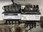
For all to see on how bad this Globalization Horse**** has gotten - one picture says it all...

70723822_447493992522266_6002687107963813888_n.jpg

The left Transformer is from Siemens with a 50VA Rating which I bought 25 Years ago - the right transformer is a new Hammond Transformer used as T2 with a 100VA rating

Now look close - THE CORE OF THE NOWADAYS 100VA IS THE SAME SIZE AS THE OLD 50VA

So, we use a 50VA and sell it to the customer as a 100VA and tell the customer that it is OK to that the transformer will heat up by 80C above ambient when fully loaded - This is mother ****ing bull****!!!!!!!!!!

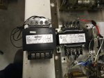
This is the difference in core size when compared to my 25 year old 150VA rated Transformer.....

70413659_513886336058056_8868138697711681536_n.jpg


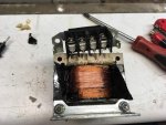
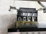
A smaller core is not necessarily bad, but when I removed the plastic cover to reduce our Transfer Ratio, then the whole story came to light:

The wire gauge on the 100VA is the same as on the 50VA - this sure is asking for a lot of trouble......

69842883_372726550282289_6471933953161822208_n.jpg69892512_1338401739655613_8077563444766703616_n.jpg


Result: We need to use a 250VA Transformer today to drive a 100VA load without heat built up.

Now before any one asks, this issue here pertains ONLY TO NEW TRANSFORMERS MADE TODAY AND HAS NOTHING TO DO WITH THE OLD ORIGINAL TRANSFORMER T2 BURNING UP! THIS WAS CAUSED BY A FAULTY C2 CAPACITOR!
 

peapvp

Well-known member
Steel Soldiers Supporter
1,115
1,229
113
Location
Basehor, KS
You may want to bring this to the attention of the administrator....

Otherwise we can hope only that any interested person is going to read all post of this thread or they may wind up with the 100VA Transformer in their A11....

**** happens, even more so today...

Yes I used it before to edit, but I guess it is only good for that day.
I went to page 10 and the edit tab was not there.
Kris
 

peapvp

Well-known member
Steel Soldiers Supporter
1,115
1,229
113
Location
Basehor, KS
Replacement Transformer and Kris’s A11 repair - final validation

So, now you know that I am old enough to blow a gasket now and then....

Anyway, lets proceed to the good news and the conclusion of the repair of Kris's A11 Unit.

The first thing I did today, after Brian posted the requested measurements, was to proceed to actually test Kris's A11 with full Voltage applied to the 100VA replacement transformer and compare the results.

Thank you again Brian for your assistance in this matter as this was extremely helpful

Now, to refresh our memory:

The original T2 Transformer had a Transfer Ratio of 208VAC to 128VAC that is 128VAC on Terminal X1 and X3 when 208VAC is applied to Terminals H1 and H2 = 1.625:1

The primary constant load on this system are the two large 55 Watt Resistors on the A11 Unit R1 100 Ohm and R2 510 Ohm

This gives us a constant resistive load of app 70VA + switching losses which are in the 30VA to 50 VA range

Total constant power 100VA to 120 VA which is a bit more then +/- 10% tolerance of the two power resistors but with C2 in the picture with +/-20% tolerance explains this variation.

So our 100VA Transformer has a transfer ratio of 2:1 or 240VAC to 120VAC

With 240 VAC applied on H1 and H4 we will get 120 VAC on X1 and X4

This would be before modification.

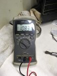
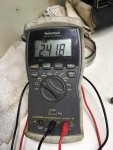
So I applied 241.8 VAC Line Voltage to H1 and H4 (with a jumper between H2/H3) and I got with the A11 connected on the secondary 108.3VAC
because of the 2:1 Transfer Ratio we should have measured 120.9VAC but because of the in the previous post explained VA rating issues with today's transformers our Secondary Voltage sagged by 12.6VAC or 9.59% which indicates that the 100VA Transformer is actually more of a 50VA to 75VA Transformer.

69934597_429373017934841_3806912415350652928_n.jpg70066245_453798758816259_2234516895350915072_n.jpg


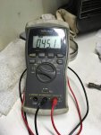
Despite this, our A11 put out 45.1 VDC on the J11 R/S Terminals and that means A11 is A OK - we are only 3 Volts short with a 9.59% lower voltage input supply!

70594223_505691899998955_1560284085887172608_n.jpg
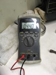
With this near 10% Voltage loss on this 100VA Transformer, our Supply current on H1 was 0.44 Amps @ 241.8 VAC = 106.392VA!


71089219_418731095441496_829047035951841280_n.jpg


Brian measured on his original T2 on H1 0.588 Amps @ 208 VAC = 122.304 VA

That is a 14.9% difference but looking at the fact that we are having a 10% lower output voltage across X1 and X4
then Brian has.

The result:

Kris's A11 is A OK and we found a much better replacement Transformer:

Hammond PH250MGJ Transformer, 250 VA, 50/60Hz

https://www.alliedelec.com/product/h...0mgj/70191777/

This transformer has a Transfer Ratio of:

387VAC to 240 VAC = 1.6125 compared to 1.625 which is a difference of -0.0125

totally negligible.

So, we got one of the 250VA's coming to Kris and the A11 is back on it's way to Texas already!

Good Day, pretty much so.

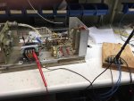
And a few final pictures of today's test:


70464592_2989088114649819_92934639789801472_n.jpg70589015_303720250479620_8461312020975714304_n.jpg70852739_2530724140330121_7960402663986692096_n.jpg71061497_741440592970267_4496585284351164416_n.jpg
 
Last edited:

Guyfang

Moderator
Staff member
Moderator
16,766
24,079
113
Location
Burgkunstadt, Germany
Some of the reasons that information like what you are after right now was not available, was the trend in the late 70's to not repair things anymore. The A11 was the clasic example. In the early 70's almost all the electrical componets were fixed at the DS, (Direct Support) level. We had at DS level all the test equipment needed to test and repair the A11. And at the end of the day, most repairs were a matter of just replacement of bad componets and then tossing the A11 into a handy gen set to "test" it. We did not have the luxury of time, like here in this thread. And that was the reason things went down hill with fixing things.

When you have to be mission capable, hours count. In the beginning, the NEW mep-004 and 005 and 006 gen sets were far from reliable. And the A11 was one of the worst componets. At one point, our HAWK battalion was non-op, due to so many gen sets having A11 problems. Repair parts were not in the system. People did not know how to test or repair them. The battalion DS was overwhelmed. So the army over reacted. The A11 became a "recoverable item". That ment when it was bad, you ordered a new one and sent the old one back into the supply system, to be sent, (hopefully) to a GS, (General Support) repair facility to be repaired. We still had the capability to repair at battalion level, but the the work went to GS. And they were overwhelmed. Soon more A11's were ordered. Defective A11's and volt reg cards, at some point in time were all shipped to one place in the states, and two places in Germany for repair. They did good work, but fast, hurry, needed were not key words for facilities run by civilians.

The he last few years I was in the army, and all during the time I worked as a contractor, (up to 2010) I only saw brand new A11's being issued. It had become cheaper and easyer to simply procure new ones. I saw piles of them in DRMO scrap piles. This was the beginning of "Pluck and Chuck" repair.
 

peapvp

Well-known member
Steel Soldiers Supporter
1,115
1,229
113
Location
Basehor, KS
The main culprit in this system is the missing fuse on the supply to T2. The SCR's back then were not that good as the silicone was not up to today's standards. Like on Brian's VR, this is a classical example of failure, two shortened SCR's and that's not a surprise when you look at the schematic, as the load is basically comprised of a LCR - with L being T2, C being C2 and then R being R2 and R3....
They guy who dreamed this design up sat in a air conditioned lab with a stable temperature of 21C at 50% to 60% RH....

Once you get this out in the field over a wide range of temperature, with the old original C2 changing it's capacitance with temperature (as any capacitor does, except for the new ones today) and then this circuit not having a temperature compensation, is basically asking for trouble to begin with.

Btw Guy, did these units tend to fail more in the summer (heat) or in the winter (cold)?

And Brian, could you please share with us which SCR's you sourced from Mouser? This would be a good part to have in stock for any A11 owner. Easy to test and easy to replace and most likely one of the components which fails most often.


Some of the reasons that information like what you are after right now was not available, was the trend in the late 70's to not repair things anymore. The A11 was the clasic example. In the early 70's almost all the electrical componets were fixed at the DS, (Direct Support) level. We had at DS level all the test equipment needed to test and repair the A11. And at the end of the day, most repairs were a matter of just replacement of bad componets and then tossing the A11 into a handy gen set to "test" it. We did not have the luxury of time, like here in this thread. And that was the reason things went down hill with fixing things.

When you have to be mission capable, hours count. In the beginning, the NEW mep-004 and 005 and 006 gen sets were far from reliable. And the A11 was one of the worst componets. At one point, our HAWK battalion was non-op, due to so many gen sets having A11 problems. Repair parts were not in the system. People did not know how to test or repair them. The battalion DS was overwhelmed. So the army over reacted. The A11 became a "recoverable item". That ment when it was bad, you ordered a new one and sent the old one back into the supply system, to be sent, (hopefully) to a GS, (General Support) repair facility to be repaired. We still had the capability to repair at battalion level, but the the work went to GS. And they were overwhelmed. Soon more A11's were ordered. Defective A11's and volt reg cards, at some point in time were all shipped to one place in the states, and two places in Germany for repair. They did good work, but fast, hurry, needed were not key words for facilities run by civilians.

The he last few years I was in the army, and all during the time I worked as a contractor, (up to 2010) I only saw brand new A11's being issued. It had become cheaper and easyer to simply procure new ones. I saw piles of them in DRMO scrap piles. This was the beginning of "Pluck and Chuck" repair.
 

KLChurch

New member
475
2
0
Location
Montgomery/TX
Some of the reasons that information like what you are after right now was not available, was the trend in the late 70's to not repair things anymore. The A11 was the clasic example. In the early 70's almost all the electrical componets were fixed at the DS, (Direct Support) level. We had at DS level all the test equipment needed to test and repair the A11. And at the end of the day, most repairs were a matter of just replacement of bad componets and then tossing the A11 into a handy gen set to "test" it. We did not have the luxury of time, like here in this thread. And that was the reason things went down hill with fixing things.

When you have to be mission capable, hours count. In the beginning, the NEW mep-004 and 005 and 006 gen sets were far from reliable. And the A11 was one of the worst componets. At one point, our HAWK battalion was non-op, due to so many gen sets having A11 problems. Repair parts were not in the system. People did not know how to test or repair them. The battalion DS was overwhelmed. So the army over reacted. The A11 became a "recoverable item". That ment when it was bad, you ordered a new one and sent the old one back into the supply system, to be sent, (hopefully) to a GS, (General Support) repair facility to be repaired. We still had the capability to repair at battalion level, but the the work went to GS. And they were overwhelmed. Soon more A11's were ordered. Defective A11's and volt reg cards, at some point in time were all shipped to one place in the states, and two places in Germany for repair. They did good work, but fast, hurry, needed were not key words for facilities run by civilians.

The he last few years I was in the army, and all during the time I worked as a contractor, (up to 2010) I only saw brand new A11's being issued. It had become cheaper and easyer to simply procure new ones. I saw piles of them in DRMO scrap piles. This was the beginning of "Pluck and Chuck" repair.
So my A11 was a pluck and chuck? LOL LOL LOL
Kris
 

Guyfang

Moderator
Staff member
Moderator
16,766
24,079
113
Location
Burgkunstadt, Germany
Peter,

This gen set did well in El Paso Texas, for A11 problems. Or any warm to hot place. I saw lots of this kind of problem in Germany. Wet and cold.

On the whole. The most often failures were:

1. Day tank float.
2. A11. 98% the volt reg card.
3. S9, Overspeed switch.
4. S/P relay box. Relays or burnt componets and traces on the back of the A5 card. Start relay.
5. A4 card in control cube. K1 relay mostly, along with burnt componets/ traces on back side if the card.
6. Thermal watt converter and frequency transducer in control cube.
7. 24 volt alternater. Easy problem, easy fix.
8. CB2 output contactor. Easy problem, easy fix.
9. And last but not least, lead acid batteries. The army just never could get it right, with batteries. We spent more money on batteries, then on the B1 bomber fleet. I could have kissed the inventor of Optima batteries.

Well, one more area. Cooling. The cooling loovers are controlled by a thermostat built in to the bottom output of the radiator. It's supposed to be filled with bees wax, and opens and closes the loovers. It not an absolute show stopper, as there is a manual lever that you can use to open and close the loovers in case the darned thing fails. There is a rope next to it to hold it open. When you run the set under load, after 5-6 minutes the loovers should begin to open. After a while the loover will open all the way, under normal running conditions. If the loovers do not move smoothly with the manual control lever, loosen the bolt and maybe lube the arm a bit. This fixes 95% of the overheating problems. If the element fails, you can still find, but not often, the element in flee bay, or other places like that. NEVER run the set long time periods with the side doors open. Only leave the control cube, if you want, and the cooling doors below it, open. If you keep the fuel clean, filters changed, oil changed and good batteries in it, this is a very dependable set. Don't let my list scare you. I have run these things 24/7 for a month or two, and they stood the test.
 

flydude92

Member
117
9
18
Location
Waterville, Ohio
The SCR's back then were not that good as the silicone was not up to today's standards.
Like on Brian's VR, this is a classical example of failure, two shortened SCR's and that's not a surprise when you look
at the schematic, as the load is basically comprised of a LCR - with L being T2, C being C2 and then R being R2 and R3....


The SCR’s I ordered are from Vishay #VS-2N689 Mouser #884-2N689 (didn’t see a datasheet)

Interesting you mentioned the problems with the SCR’s.

I bought an NOS VR on EBay a couple years ago. I tried it
shortly after I purchased it. It worked great for about 3 seconds then the generator
shut down with an over voltage condition. I put it away until I had time to deal with it.

I checked it out this morning.
I ran the three tests today and the 2[SUP]nd[/SUP] test failed. I was expecting 48 vdc and got 31.3 vdc.

I used the good VR to test against the bad one. Resistance comparisons loosely pointed to
a bad Q1. I also compared voltages at the junction of R5 / VR1 and R18 / R19. Got
a couple readings that were about 40% to low compared to the working VR. I was suspecting
the SCR’s but hesitated until I saw your comment about the quality of silicon used in SCR's many
years ago.

I had a couple extra so I replaced them. I now get 47.5 vdc.

BUT after a couple minutes the voltage started to fluctuate between roughly 45.5 - 47.5.

The problem seems to be heat related. When I spray the area around U1 with cold air it stops fluctuating for
another couple minutes. I’m going to try to narrow it down to at least a couple components.

Brian
 

peapvp

Well-known member
Steel Soldiers Supporter
1,115
1,229
113
Location
Basehor, KS
Brian,

good choice on the SCR's from Vishay!

Here is the Datasheet:

View attachment vs-2n681-2n5205series.pdf

I marked a few things to check in the pic below. This is a typical Cap or Zener issue. My best guess would be one of the small electrolytic's is going bad, but could be a film too. We call this behavior motor boating when a cap starts to go bad - this is a similar pattern of what C2 looks like it when it starts to fail.

It is usually a cap used to stabilize a pin on semi conductor which has connection to Ground Plane and when they dry out they start to shorten the pin of the semi conductor to Ground. Little at first like in your case. The cap will heat up in the process because of the changing internal resistance or ESR which is normally near infinite Ohm at DC. So, you would need a ESR tester, capacitance check alone will not tell the full tail here.

But it also could be a deteriorating Zener where the silicone is starting to break down - that causes Voltage Fluctuations as well
Brian 1.jpg


The SCR’s I ordered are from Vishay #VS-2N689 Mouser #884-2N689 (didn’t see a datasheet)

Interesting you mentioned the problems with the SCR’s.

I bought an NOS VR on EBay a couple years ago. I tried it
shortly after I purchased it. It worked great for about 3 seconds then the generator
shut down with an over voltage condition. I put it away until I had time to deal with it.

I checked it out this morning.
I ran the three tests today and the 2[SUP]nd[/SUP] test failed. I was expecting 48 vdc and got 31.3 vdc.

I used the good VR to test against the bad one. Resistance comparisons loosely pointed to
a bad Q1. I also compared voltages at the junction of R5 / VR1 and R18 / R19. Got
a couple readings that were about 40% to low compared to the working VR. I was suspecting
the SCR’s but hesitated until I saw your comment about the quality of silicon used in SCR's many
years ago.

I had a couple extra so I replaced them. I now get 47.5 vdc.

BUT after a couple minutes the voltage started to fluctuate between roughly 45.5 - 47.5.

The problem seems to be heat related. When I spray the area around U1 with cold air it stops fluctuating for
another couple minutes. I’m going to try to narrow it down to at least a couple components.

Brian
 

peapvp

Well-known member
Steel Soldiers Supporter
1,115
1,229
113
Location
Basehor, KS
Brian,

I have one more suggestion for you. I don't know on how many DMM's you have available, but if possible, I would hook up one DMM in AC Range on T2 X1 and X3 and one on T2 H1 AC Current besides the output measurement in DC on J11 R/S when testing VR Boards.

You can use the known good VR as reference for this - On X1 / X3 you should measure ~ 128VAC +/- 4VAC with 208VAC on H1 / H2 (this transformer business is not an exact science...)

With your original T2 the X1 / X3 AC Voltage should not drop by more then 4 VAC with a good VR Board and a good C2

If it it does, then this will indicate issues with C2 and/or the VR Board - if this Voltage is within +/- 4 VAC then the entire lower DC Voltage on J1 R/S is solely coming from the VR Board

Would be interesting if you could share your results here! Thanks Peter


The SCR’s I ordered are from Vishay #VS-2N689 Mouser #884-2N689 (didn’t see a datasheet)

Interesting you mentioned the problems with the SCR’s.

I bought an NOS VR on EBay a couple years ago. I tried it
shortly after I purchased it. It worked great for about 3 seconds then the generator
shut down with an over voltage condition. I put it away until I had time to deal with it.

I checked it out this morning.
I ran the three tests today and the 2[SUP]nd[/SUP] test failed. I was expecting 48 vdc and got 31.3 vdc.

I used the good VR to test against the bad one. Resistance comparisons loosely pointed to
a bad Q1. I also compared voltages at the junction of R5 / VR1 and R18 / R19. Got
a couple readings that were about 40% to low compared to the working VR. I was suspecting
the SCR’s but hesitated until I saw your comment about the quality of silicon used in SCR's many
years ago.

I had a couple extra so I replaced them. I now get 47.5 vdc.

BUT after a couple minutes the voltage started to fluctuate between roughly 45.5 - 47.5.

The problem seems to be heat related. When I spray the area around U1 with cold air it stops fluctuating for
another couple minutes. I’m going to try to narrow it down to at least a couple components.

Brian
 

KLChurch

New member
475
2
0
Location
Montgomery/TX
I submitted a "report post" on post #86 referencing an error in the transformer capabilities and also referencing to go to post #271 for the correct transformer.
I have never done this before so I guess we will see how the report works. This was suggested by SS to do so.
Kris
 

flydude92

Member
117
9
18
Location
Waterville, Ohio
I marked a few things to check in the pic below. This is a typical Cap or Zener issue. My best guess would be one of the small electrolytic's is going bad, but could be a film too. We call this behavior motor boating when a cap starts to go bad - this is a similar pattern of what C2 looks like it when it starts to fail.
It is usually a cap used to stabilize a pin on semi conductor which has connection to Ground Plane and when they dry out they start to shorten the pin of the semi conductor to Ground. Little at first like in your case. The cap will heat up in the process because of the changing internal resistance or ESR which is normally near infinite Ohm at DC. So, you would need a ESR tester, capacitance check alone will not tell the full tail here.
But it also could be a deteriorating Zener where the silicone is starting to break down - that causes Voltage Fluctuations as well
Peter,

I read your post just after I tested the board but thank you very much for the information.

I purchased this generator in 2012 and in 2013 it had an over voltage error but the generator
didn’t shut down. I documented the problems on this site at that time. I had corrosion on most of
the diodes. To repair it I sourced all the parts on the VR board including the connector and
stocked at least 1 of each just in case I needed them. (the connector was partially melted)
This is why I have so many parts.

To test parts that I suspect are affected by heat I put an ohm meter on them and heat them up.
I’m not sure it’s a normal test procedure but it works. I’m not worried about the value shown
during the test just how it reacts to the heat. I heated each part around U1 and was surprised
that most of the resistors never changed value. VR3 stayed solid and VR1 changed value a little.
When I heated CR9 the value changed up and down a lot. When it cooled it returned to normal.
I removed CR9 and checked it with the same results.
I only changed CR9 so I would know if that fixed it and it did.

The main reason I change all the caps is their age, to eliminate future cap problems and they are
inexpensive. I ran out of C6 caps though.

I then replaced VR1, VR3, R12 (it changed when heated) they are only a few cents and
easy to replace.

I get a solid 45.5 vdc instead of 48. I’m not sure if that is a problem but it is within 10%.

CR9 was one of the components I had trouble sourcing.
I replaced it with a 1N4002 but can’t remember how I got to this diode.

Brian
 
Top
AdBlock Detected

We get it, advertisements are annoying!

Sure, ad-blocking software does a great job at blocking ads, but it also blocks useful features of our website like our supporting vendors. Their ads help keep Steel Soldiers going. Please consider disabling your ad blockers for the site. Thanks!

I've Disabled AdBlock
No Thanks