• Steel Soldiers now has a few new forums, read more about it at: New Munitions Forums!

  • Microsoft MSN, Live, Hotmail, Outlook email users may not be receiving emails. We are working to resolve this issue. Please add support@steelsoldiers.com to your trusted contacts.

MEP-004A, No output

peapvp

Well-known member
Steel Soldiers Supporter
1,105
1,214
113
Location
Basehor, KS
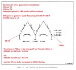
This would be the necessary mods for 120/240 to work

WARNING:
However each generator coil T number has to be double checked and this is extremely important:

Each coil beginning and end has to be accurately determined and verified with the T numbers in the drawings for this to work right

OTHERWISE YOU WILL HAVE SMOKE COMING OUT OF YOUR GENERATOR...............

mep003a2.jpg
 

Guyfang

Moderator
Staff member
Moderator
16,690
23,888
113
Location
Burgkunstadt, Germany
Any time, you do any thing, to TB1, you need to check not once, not twice, but three times, the wire and terminal numbers. AND, you need to check to see if when you put the TB1 beck in place, that no wire or terminal even comes close to another wire, terminal or the standoffs for the TB. You need to see that no cable is pinched between a terminal. Because if you get anything wrong, you will witness a light show to end all light shows. And the sound you hear will remain with you for the rest of your days.
 

KLChurch

New member
475
2
0
Location
Montgomery/TX
disconnect.jpg

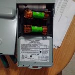
This is the fused disconnect switch I bought to be installed between the 30KVA transformer and my house input.
It was advised that I install 45 amp fuses for the mep 004
Kris
 

KLChurch

New member
475
2
0
Location
Montgomery/TX
Any time, you do any thing, to TB1, you need to check not once, not twice, but three times, the wire and terminal numbers. AND, you need to check to see if when you put the TB1 beck in place, that no wire or terminal even comes close to another wire, terminal or the standoffs for the TB. You need to see that no cable is pinched between a terminal. Because if you get anything wrong, you will witness a light show to end all light shows. And the sound you hear will remain with you for the rest of your days.
Are you stating from experience? LOL
 

flydude92

Member
117
9
18
Location
Waterville, Ohio
Short Story:

My wife woke me up at 03:15 this morning and said we lost power. We have no clue how long
it’s been off since our very loud warning buzzer fell off the refrigerator in the basement and was
covered by a bunch of stuff.

We have a sump pump with a backup battery but don’t really know how long it will last before
the battery dies and the basement floods.

But I’m not worried, I have a generator!!!!!!

I start the generator, hold the switch up as usual until I have power and when I let go, NO POWER.

Of course I felt I must have done something wrong so I try again with the same results.

Since the exciter/regulator (A11) assembly was the only thing I’ve been working on I picked up the one on the
dining room table, that had no covers and had the regulator board I just worked on installed. I unplugged the test
cables and installed it. It ran perfectly.

My wife hates the dining room table as a work bench of course,
but seems a little less annoyed since we now have a repaired backup.

Soooooooo thank you ‘KLChurch’ for starting this thread and not giving up, ‘Guyfang’ for your help
with this thread and your years of support and of course ‘peapvp’ for your detailed information relating
to repair, diagnostics and support of the generators.

The A11 assembly that failed was the one I had installed for the last few years. The 1 amp fuse blew.

I just ran all three tests and they haven’t changed.

I assume either I had a bad fuse or there may be some unknown startup surge although the backup also
had a 1 amp fuse.


Brian
 

peapvp

Well-known member
Steel Soldiers Supporter
1,105
1,214
113
Location
Basehor, KS
Brian,

that may have been the fuse which blew when you tested the VR with the bad SCR's and you told us that the fuse blew.

Peter (PEAPVP)

Short Story:

My wife woke me up at 03:15 this morning and said we lost power. We have no clue how long
it’s been off since our very loud warning buzzer fell off the refrigerator in the basement and was
covered by a bunch of stuff.

We have a sump pump with a backup battery but don’t really know how long it will last before
the battery dies and the basement floods.

But I’m not worried, I have a generator!!!!!!

I start the generator, hold the switch up as usual until I have power and when I let go, NO POWER.

Of course I felt I must have done something wrong so I try again with the same results.

Since the exciter/regulator (A11) assembly was the only thing I’ve been working on I picked up the one on the
dining room table, that had no covers and had the regulator board I just worked on installed. I unplugged the test
cables and installed it. It ran perfectly.

My wife hates the dining room table as a work bench of course,
but seems a little less annoyed since we now have a repaired backup.

Soooooooo thank you ‘KLChurch’ for starting this thread and not giving up, ‘Guyfang’ for your help
with this thread and your years of support and of course ‘peapvp’ for your detailed information relating
to repair, diagnostics and support of the generators.

The A11 assembly that failed was the one I had installed for the last few years. The 1 amp fuse blew.

I just ran all three tests and they haven’t changed.

I assume either I had a bad fuse or there may be some unknown startup surge although the backup also
had a 1 amp fuse.


Brian
 

KLChurch

New member
475
2
0
Location
Montgomery/TX
Brian
Glad this helped you and your gen
So it maybe wise to put the fuse in a better location than inside the box? Easier to find out what's going on?
Kris
 

KLChurch

New member
475
2
0
Location
Montgomery/TX
Peter,
Since you sell auto start retrofits, maybe a fuse blown kit that a person can install on the fault indicator box?
Just a thought.
Kris
 

peapvp

Well-known member
Steel Soldiers Supporter
1,105
1,214
113
Location
Basehor, KS
Kris,

thank you. Something we could ad for few bucks.

Brian,

I forgot, that was the 3 Amp Fuse which blew when you tested the other VR Board.

There is probably some spiking happening when it switches from Field Flash to VR Excitation - a 2Amp or 3Amp Fuse would work fine and will still protect T2 as we proved that with your VR Board.

Peter

Peter,
Since you sell auto start retrofits, maybe a fuse blown kit that a person can install on the fault indicator box?
Just a thought.
Kris
 

flydude92

Member
117
9
18
Location
Waterville, Ohio
Brian,
The very last test I would like to know/perform:
With the Genset set to 120/208 on the reconnection board and A11 installed and running and rheostat set to 125vac
what would be the actual AC Input Voltage on T2 H1 / H2 and what would be the output voltage AC and DC on J13 R/S F1/F2
This would tell us exactly of what A11 would do in the reconnection board setting for 240/416 without actually changing the reconnection board
I would think that the voltages input output in test 2 will be exactly a little bit less then half of Test 2 in the 120/208 configuration.
Peter,

T2 - H1/H2 = 216.9

T2 - X1/X3 = 126.9

T2 - X2/X3 = 63.4

T2 - X2/X1 = 63.3

F1/F2 = 3.0

I hope I got it right this time.

Brian
 

Guyfang

Moderator
Staff member
Moderator
16,690
23,888
113
Location
Burgkunstadt, Germany
Are you stating from experience? LOL
Yes sir. Three times. One time I screwed it up. Another time someone else did, and told me he, "had check it, shut up, put it back together." When you are a SP/4, and a SSG tells you to put it back together, you do just that. I laughed for days!

Another time, I pulled an axe out of a gen set, (it was inside on top of the fuel tank, where we stored them during field problems.) to set the ground rod. Yes, it was running without one. The blade, when I drew it out, cut all three load wires, at once. Keep in mind, this is BEFORE CB2. There is NOTHING to protect you. The flame, sparks, smoke and sound was about a foot from my face. My partner thought I had been killed, and left the scene of the crime. The short, caused the gen set to die, after a while. a long while. I wanted to turn it off, but was having a hard time seeing anything, due to the "flash" blinding from the sparks. Yes, I wanted to change my underwear.
 

Guyfang

Moderator
Staff member
Moderator
16,690
23,888
113
Location
Burgkunstadt, Germany
Brian
Glad this helped you and your gen
So it maybe wise to put the fuse in a better location than inside the box? Easier to find out what's going on?
Kris
You know, this is a darn fine suggestion. I would drill a hole to the side of the two C-Plugs, and install a fuse holder like on the fault indicator. Handy, and in the open where you can see it! Darned fine idea!
 

Guyfang

Moderator
Staff member
Moderator
16,690
23,888
113
Location
Burgkunstadt, Germany
Peter,
Since you sell auto start retrofits, maybe a fuse blown kit that a person can install on the fault indicator box?
Just a thought.
Kris
Tis would require using, (if there is unused pins) extra wire from the A11, to the Sp-Relay box and then to the A9 fault indicator. Lots of work.
 

KLChurch

New member
475
2
0
Location
Montgomery/TX
Peter,
Got the a11 back today. Thank you.
The trans for it will be here in a couple of days.
So I will install the fuse the way Guy suggested and take a pic.
Kris
 

peapvp

Well-known member
Steel Soldiers Supporter
1,105
1,214
113
Location
Basehor, KS
Brian,

Thank You! You sure did it correctly.

126.9VAC across is exactly what I expected with output set to 125VAC because of the drop of about 0.8V across each SCR so, 1.6V higher.

This also tells me and confirms that when you change the voltage reconnection board from 120/208 to 240/416 that H1 and H2 are now across only one coil as the coils are reconfigured from parallel to serial, so it's half of 416 = 208 and not from any one phase to neutral which would be 240VAC

Again, supplying only 120 VAC on H1 / H2 will not damage T2, but instead of getting 120/208 after field flash you would get only 60/104VAC and the Genset would probably shut down because of a under voltage condition.

Only question, is measured Voltage on F1/F2 AC or DC? I guess it would be AC?

And I guess we can call Guy now Sparky! As they say in Germany Guy:

Wo gehobelt wird, da fallen Späne......

[Where wood is chopped, splinters must fall]

and


It ain't over till the fat Lady sings.......

Thanks Peter

Peter,

T2 - H1/H2 = 216.9

T2 - X1/X3 = 126.9

T2 - X2/X3 = 63.4

T2 - X2/X1 = 63.3

F1/F2 = 3.0

I hope I got it right this time.

Brian
 

peapvp

Well-known member
Steel Soldiers Supporter
1,105
1,214
113
Location
Basehor, KS
Kris,

You could also mount a 208/240VAC Panel light in parallel to the Fuse, this way if the Fuse goes out the Light comes On

Peter


Peter,
Got the a11 back today. Thank you.
The trans for it will be here in a couple of days.
So I will install the fuse the way Guy suggested and take a pic.
Kris
 

Guyfang

Moderator
Staff member
Moderator
16,690
23,888
113
Location
Burgkunstadt, Germany
Kris,

You could also mount a 208/240VAC Panel light in parallel to the Fuse, this way if the Fuse goes out the Light comes On

Peter
The problem is adding extra wires/circuits. If there is not unused wires in the harnesses, then you have to jurry rig something. It makes it messy. Easy to damage. We need to look at the plugs. The TM's do not tell you if there are unused wires.

Yes, I have seen the light! It will make a constipated man run for the hills!

The voltage on wires F1 and F2 should be DC.
 
Last edited:
Top